TSL2561-Brancher
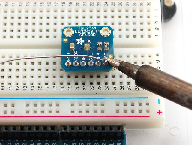
This is an easy sensor to get started with. The breakout board comes with a 6-pin header strip that you can use to plug the sensor into a breadboard or perfboard. Simply plug the header into a solderless breadboard with the long pins down and short pins up. Place the sensor on top so each pad has a header pin in it and solder the two together.
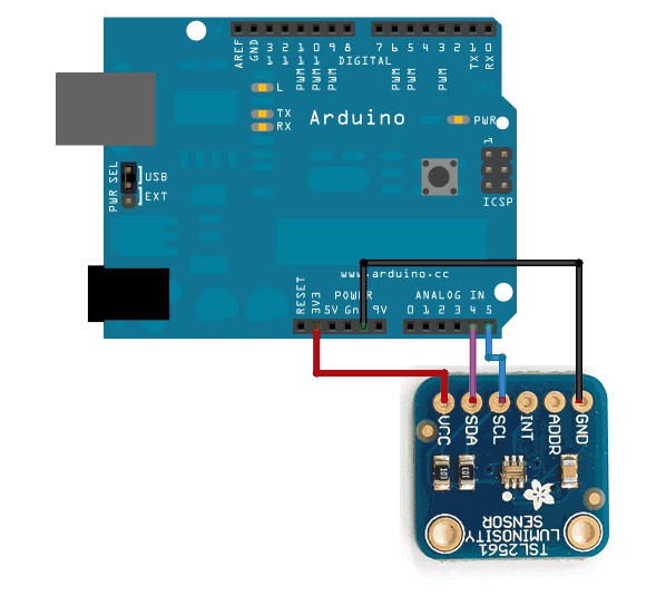
Next we will connect it to our microcontroller. In this case we'll be using an Arduino but nearly any microcontroller can be used by adapting our code
- Connect the VCC pin to a 3.3V power source. The sensor cannot be used with anything higher than 3.3V so don't use a 5V supply!
- Connect GND to the ground pin.
- Connect the i2c SCL clock pin to your i2c clock pin. On the classic Arduino Uno/Duemilanove/Diecimila/etc this is Analog pin #5
- Connect the i2c SDA data pin to your i2c data pin. On the classic Arduino Uno/Duemilanove/Diecimila/etc this is Analog pin #4
Unfortunately, the i2c lines on most microcontrollers are fixed so you're going to have to stick with those pins
| You may be wondering, how is it OK to connect a 3.3V chip like the TSL2561 to 5.0V data pins like the Arduino? Isn't that bad? Well, in this specific case its OK. I2c uses pullup lines to the 3.3V power pin, so the data is actually being sent at 3.3V. As long as all the sensors/device on the i2c bus are running on 3.3V power, we're fine. However, don't use a 5.0v powered i2c device (like the DS1307) with pullups at the same time as a 3.3V device like the TSL2561! If you want to use this sensor with a datalogger that uses the DS1307, remove any/all of the pullup resistors from the DS1307 SDA/SCL pins. The pullups built into the TSL2561 will then be active and keep the voltage at 3.3V which is safe for both the RTC and the sensor. |
You don't need to connect the ADDR (i2c address change) or INT (interrupt output) pins.
The ADDR pin can be used if you have an i2c address conflict, to change the address.
- Connect it to ground to set the address to 0x29,
- connect it to 3.3V (vcc) to set the address to 0x49 or
- leave it floating (unconnected) to use address 0x39.
The INT pin is an ouput from the sensor used when you have the sensor configured to signal when the light level has changed. We don't have that code written in this tutorial so you don't have to use it. If you do end up using it, use a 10K-100K pullup from INT to 3.3V (vcc)
Réalisé par LadyAda Pour AdaFruit Insdustries.
Source: [1]
Traduit avec l'autorisation d'AdaFruit Industries - Translated with the permission from Adafruit Industries - www.adafruit.com
Toute référence, mention ou extrait de cette traduction doit être explicitement accompagné du texte suivant : « Traduction par MCHobby (www.MCHobby.be) - Vente de kit et composants » avec un lien vers la source (donc cette page) et ce quelque soit le média utilisé.
L'utilisation commercial de la traduction (texte) et/ou réalisation, même partielle, pourrait être soumis à redevance. Dans tous les cas de figures, vous devez également obtenir l'accord du(des) détenteur initial des droits. Celui de MC Hobby s'arrêtant au travail de traduction proprement dit.

