Différences entre versions de « ADAFRUIT-AUDIO-FX-PinOut »
| Ligne 26 : | Ligne 26 : | ||
== Port Série == | == Port Série == | ||
| + | If you want to control the Sound Board over UART Serial, you can do so by using the TX, RX and UG pins. | ||
| + | |||
| + | * '''TX''' - this is the serial OUT from the board. 3.3V logic | ||
| + | * '''RX''' - this is the serial INTO the board. We add some level shifting so you can use 3-5V logic. | ||
| + | * '''UG''' - the UART/GPIO selector pin. Pulled high for default GPIO trigger mode. Tie to ground and reset the board for UART mode. | ||
| + | |||
| + | {{ADFImage|ADAFRUIT-AUDIO-FX-PinOut-20.jpg}} | ||
| + | |||
| + | == Ajuster le volume == | ||
| + | These are two extra inputs that can be used to adjust the volume in GPIO trigger mode only. Connect buttons that go from each pin to ground, when the button is pressed, the volume will decrease or increase | ||
| + | |||
| + | The volume is '''not''' stored during power cycling or resets, so it will have to be re-applied after restarts. | ||
| + | |||
| + | {{ADFImage|ADAFRUIT-AUDIO-FX-PinOut-30.jpg}} | ||
| + | |||
| + | == Sorties audio == | ||
| + | If you don't want to use the headphone jack, connect your amplifier to the Right, Left and Ground pins. These are line level outputs for headphones of about 30 ohms, not for big speakers! There are output DC blocking capacitors so you can safely connect directly to any kind of amplifier | ||
| + | |||
| + | == Broches de déclenchement == | ||
| + | Finally, we're at the trigger pins! These are the 11 inputs that can be used to trigger audio playing. We'll go over how to set the file for each pin in a later page. | ||
| + | |||
| + | Each pin has a pullup resistor, use a button/switch to connect to ground when pressed in order to 'trigger' it. The board has debouncing logic built in. | ||
| + | |||
| + | {{ADFImage|ADAFRUIT-AUDIO-FX-PinOut-40.jpg}} | ||
| + | |||
| + | == Autres broches == | ||
| + | We have a few other pins you may be curious about | ||
| + | |||
| + | * '''Rst''' - this is the reset pin, you probably don't need to use this pin but when tied to ground it resets the board. | ||
| + | * '''Act''' - this is the Activity pin, which goes low when an audio file is played | ||
| + | * '''CS''' - this is the chip select line for the onboard flash chip, do not connect anything to it! We use it for programming the chip during manufacture! | ||
| + | |||
| + | {{ADFImage|ADAFRUIT-AUDIO-FX-PinOut-50.jpg}} | ||
| + | |||
{{ADAFRUIT-AUDIO-FX-TRAILER}} | {{ADAFRUIT-AUDIO-FX-TRAILER}} | ||
Version du 29 décembre 2015 à 15:24
|
|
En cours de traduction/élaboration. |
Brochage
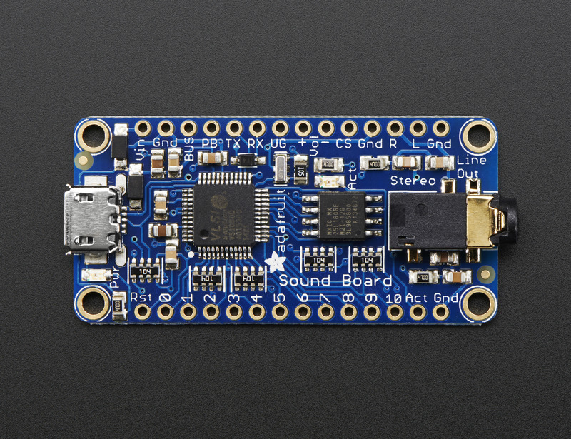
The top and bottom pin sets are the same for the headphone and amplifier out version of the sound board, we just use the headphone version for the photos below
Crédit: AdaFruit Industries www.adafruit.com
The Sound Board has a lot of pins, but we can group them into chunks, lets go through each kind of group in order to understand all the stuff you can do.
Crédit: AdaFruit Industries www.adafruit.com
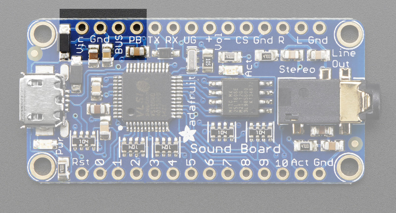
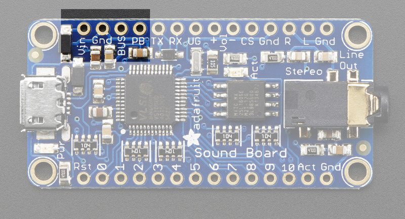
Alimentation
There's a couple power pins in the top. This is what you'll use to power the Sound Board in your project.
- Vin - This is the primary 'battery' power input pin. Power with 3-5.5 VDC
- GND - there's a couple ground pins but we suggest this one for power input. The others can be used for signal grounds
- BUS - this is the 5V that comes from the USB connector. We break this out in case you want to use it to say charge a LiPoly battery (See the Powering It page!)
- PB - this is the 'Power Button' pin, which we use for testing. Just leave it disconnected for use.
In general, you'll only want to power through the Vin and GND pins. The Vin input pin is polarity protected and can use 3V-5.5V DC input. If you want to use a larger voltage, you'll need another regulator that can bring the voltage down to 3-5V DC
Crédit: AdaFruit Industries www.adafruit.com
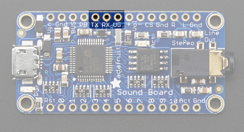
Port Série
If you want to control the Sound Board over UART Serial, you can do so by using the TX, RX and UG pins.
- TX - this is the serial OUT from the board. 3.3V logic
- RX - this is the serial INTO the board. We add some level shifting so you can use 3-5V logic.
- UG - the UART/GPIO selector pin. Pulled high for default GPIO trigger mode. Tie to ground and reset the board for UART mode.
Crédit: AdaFruit Industries www.adafruit.com
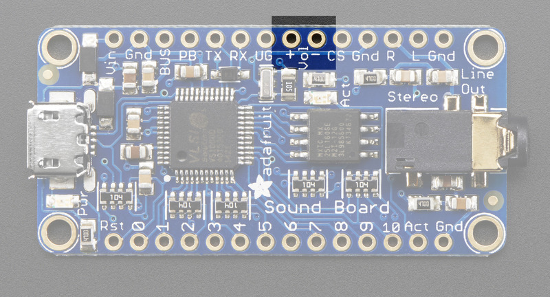
Ajuster le volume
These are two extra inputs that can be used to adjust the volume in GPIO trigger mode only. Connect buttons that go from each pin to ground, when the button is pressed, the volume will decrease or increase
The volume is not stored during power cycling or resets, so it will have to be re-applied after restarts.
Crédit: AdaFruit Industries www.adafruit.com
Sorties audio
If you don't want to use the headphone jack, connect your amplifier to the Right, Left and Ground pins. These are line level outputs for headphones of about 30 ohms, not for big speakers! There are output DC blocking capacitors so you can safely connect directly to any kind of amplifier
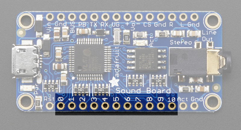
Broches de déclenchement
Finally, we're at the trigger pins! These are the 11 inputs that can be used to trigger audio playing. We'll go over how to set the file for each pin in a later page.
Each pin has a pullup resistor, use a button/switch to connect to ground when pressed in order to 'trigger' it. The board has debouncing logic built in.
Crédit: AdaFruit Industries www.adafruit.com
Autres broches
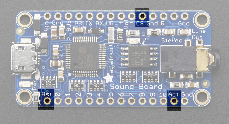
We have a few other pins you may be curious about
- Rst - this is the reset pin, you probably don't need to use this pin but when tied to ground it resets the board.
- Act - this is the Activity pin, which goes low when an audio file is played
- CS - this is the chip select line for the onboard flash chip, do not connect anything to it! We use it for programming the chip during manufacture!
Crédit: AdaFruit Industries www.adafruit.com
Source: Adafruit Audio FX Sound board Crédit: AdaFruit Industries
Créé par Ladyada pour AdaFruit Industries.
Traduit par Meurisse D. pour MCHobby.
Toute référence, mention ou extrait de cette traduction doit être explicitement accompagné du texte suivant : « Traduction par MCHobby (www.MCHobby.be) - Vente de kit et composants » avec un lien vers la source (donc cette page) et ce quelque soit le média utilisé.
L'utilisation commercial de la traduction (texte) et/ou réalisation, même partielle, pourrait être soumis à redevance. Dans tous les cas de figures, vous devez également obtenir l'accord du(des) détenteur initial des droits. Celui de MC Hobby s'arrêtant au travail de traduction proprement dit.
Traduit avec l'autorisation d'AdaFruit Industries - Translated with the permission from Adafruit Industries - www.adafruit.com