ENG-CANSAT-ANTENNA
Introduction
What ever you do, the antenna is always one of the most sensitive component when working in the radio area.
The following schema shows how to wire the RFM69HCW to transmit data.

As you can see, the antenna is made of a simple wire.
Remove the wire and the data would not transmit at 1 meter of distance, even on the same desk!
Remember, the antenna is the key to transmit data over a long distance!
Antenna connector
The radio modules usually offer a spot to solder antenna.
With the RFM69HCW the antenna spot allow you to connect an antenna in 3 different ways.

Later on, you would focus on antenna choice:
- A wire inside the antenna hole (also said a wire dipole or simple dipole).
- A µFl connector to plug antenna.
- A PCB SMA connector also to plug other kind of antenna.
The cheapest antenna is the wire antenna (simple dipole) and the best option is the SMA connector (also mode heavy).
The µFl connector (also named uFl) is looking to this:

A PCB SMA connector is looking to this:

Ground Station - Yagi Antenna
While reading some resources on the QSO magazine (Magazine from Belgian Radio Amateur Association written in dutch and french), we did discover a Yagi Antenna tuned for 433Mhz.

Source: QSO Magazine via this publication - click to enlarge
This antenna was engineered from the "Cheap Yagy" (pdf), issue from the "Controlled Impedance 'Cheap' Antennas" article written by Kent Britain WASVJB.
A simple rule of three can be used to adapt the antenna to other frequencies (the antenna was already adapted from a 432 Mhz design).
6 or 11 elements
The Yagi antenna showed here upper does have 6 elements.
From a deeper read of the QSO magazines series, we learned that 6 elements Yagi can offer a gain up to 11.2 dBi.
It seems that the 11 elements Yagi (see original document) will double the gain. Whoaw!!!
About Yagi Antenna
Here some very basic information about Yagi antenna. It brings fundamental concepts that you will deal off with such antenna.
Radiation Pattern
The radiation pattern is the direction or directions where the signal will be emitted (or received).
So for a given transmission power, a directional antenna would send the signal further than an hemisphere antenna. Indeed, directional antenna would concentrate all the power is one direction where as hemisphere antenna would spread the same power all around.
The Yagi antenna does support several radiation pattern but "Yagi" is often used in place of "Directional Yagi".
- Isotropic Antenna : radiate the same in all the direction.
- Directional Antenna (or Beam Antenna) : radiate most of its power in one or more direction. This increase the performances in the direction while reducing the interference coming from the other directions.
- Omni Directional antenna : uniformly radiates the power in one plan. With a directive pattern shape in perpendicular plane. This antenna radiates equally in all the directions and have some angle of elevation (dixit elprocus.com)
- Hemispherical antenna : radiates one half of the hemisphere (the lower or the upper one)
Common Design
The antenna lengths and spacing are depending on the wavelength to capture.

Source: design of Yagi Uda Antenna
- Directors : used to drive the signal in the given direction. Those directors are usually shorter than driven element (about 5%).
- Driven element : is the element that capture or emit the signal.
- Reflector : reflect the signal toward (or coming from) the driven element. The reflector is larger than driven element (about 5%).
Because of the antenna design, the maximum of radiation is in the way of director.

Needed Material
A cheap Yagi antenna could be realised with plastic material (or wood) and some very tick wire.

However, the standard Yagy Antenna (and the best ones) are made with aluminium pipes.
Resource
- A closer look at the “black magic” of antennas, how they work, what is essential, and how to test them (Youtube)
Very pratical and affordable video. They explain the power lost (or gain) in the antenna, in the antenna cable. - Yagi Uda Antenna (elprocus.com)
- Advantages & disadvantages of YAGI antenna (rfwireless-world.com)
- RFM69HCW antenna hookup guide (Sparkfun, also thread the Dipole antenna)
CanSat and Antenna
As specified by the CanSat settlement, everything should be contained within a defined volume (the Can).
So, the antenna should also fit into the volume.
However, once the can is released in the air, your project can deploy an antenna.
A well designed antenna for sending the data would also reduce the error ratio on the ground station.
Quarter WaveLength Antenna
It is possible to create a small antenna made of a simple thread of Wire.
The thickness is not especially critical but the length is very important.
The ideal Length can be calculated with the following formula:
       c
L = -------
     4 x f
Where:
- c : is the light speed (in m/s)
- f : the frequency (in hertz) for the antenna
- 4 : because it's a quarter length antenna.
So for a 433 Mhz, this will gives:
        3x10E8
L = -------------- = 0.1732m
     4 x 433*10E6
So an antenna length of 17.32 cm.
Quarter WaveLength & Polarization

Other Antennas
We encourage you to search antenna with better performance, the Dipole Antenna is one of best choice when starting (easy to do with good performance).
Being creative may offers significant advantages in antenna design. A good antenna will maximize the transmitted power to the ground station.

7 Rules for Radio Antennas

- Rule #1: Use short, high quality and thick antenna cables.
- Rule #2: An SWR below 2 is acceptable (less than 11% of power is reflected so we have much of the power available for transmission).
- Rule #3: Always connect an antenna to the sender (otherwise 100% of signal is reflected, which may kill the sender)
- Rule #4: Keep the polarization of your antennas the same way.
- Rule #5: The more dBi, the more power in one direction.
- Rule #6: With a proper antenna setup, the distance in air is not an issue if we have a line of sight.
- Rule #7: Longer is not always better for antennas. Smarter is better.
All coming from the famous video of Andreas Spiess.
What is SWR?
SWR (Standing Wave Radio) measure the performance of signal emitted in the atmosphere. This value is available on the antenna technical datasheet or can be evaluated with appropriate measurement device.
On a radio board, the signal is generated by the transceiver, flowing into the antenna cable and finally through the antenna to be emitted into the atmosphere.
Depending on the antenna, there is some rejection of the signal back to the transceiver. This means than a portion of the signal is not emitted to the air! This is why the SWR measurement is done.
A poor antenna design will have greater SWR (>2) meaning that range of transmission (or reception) will be reduced! Very bad SWR may even damage the transceiver!
The worse case is when there is no antenna, in this case, the rejection ratio is 100%. Nothing is emitted to the atmosphere and all the signal is send back to the transceiver (which may possibly destroy it!
| SWR | Description |
| 1.0-1.5 | The ideal range! an SWR under 1.5 is really great. Getting under 1.5 (closer of 1) is possible but difficult, you may consider additionnal tuning, other equipment and different mounting location. However dropping under 1.5 (to 1.0) would not increase the performance in significant manner. |
| 1.5-1.9 | This range will provide an adequate/acceptable performance. Due to installations, it's sometime impossible to get an SWR under that range. This SWR range often means that your tuned antenna is not mounted in a less-than-ideal location. To troubleshoot, search for paper dealing about "problematic antenna mounting locations". Going to from 2.0 down to 1.5 will really offer noticeable performance improvement. |
| 2.0-2.4 | While not good, this likely won't damage your radio with casual use. However, you should definitely try to improve it if you can. SWR in this range is usually caused by a poor antenna mounting location and/or a poor choice of equipment for your specific vehicle. To troubleshoot, you'll likely need to move the mounting location and/or use a more suitable antenna. It's by no means a good tuning job, but will function if you've exhausted all other troubleshooting possibilities. |
| 2.5-2.9 | Do not operate radio in this range. SWR in this range offer antenna with decreased performance. With range in 2.5 - 2.9 you may even damage the transceiver in case of long period (or frequent) transmitting. This bad SWR range may be caused by poor mounting location, poor equipment. To solve: change your location and/or antenna. |
| 3.0+ | DO NOT OPERATE RADIO IN THIS RANGE. SWR in this range would have bad performance and this will probably damage the radio when use. You SHOULD NOT transmit with a SWR levels above 3.0. This is almost always the result of a poor ground or incorrectly assembled material (it may also indicates a faulty coax, faulty antenna, SWR meter not properly attached). |
The SWR can be measured with appropriate device, it is maybe time to find a Radio Amateur club around your location.

Learn more about SWR on wearecb.com.
Getting Help from Radio Amateur
Designing and testing an antenna for long distance communication is an intensive work.
You could find some help from our Radio Amateurs friends.
To locate a Radio Amateur Club near of your home then have a look the "Maker's Maps" owned at MC Hobby.
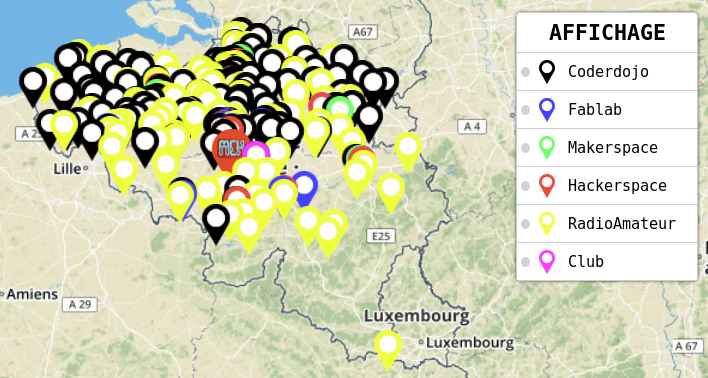
A yellow mark indicates the Radio Amateur clubs.
Written by Meurisse D. from MC Hobby - License: CC-SA-BY.