Différences entre versions de « ENG-CANSAT-CONTENT »

De MCHobby - Wiki
Sauter à la navigation Sauter à la recherche
 
(12 versions intermédiaires par le même utilisateur non affichées)
Ligne 9 : Ligne 9 :
  
 
<div style="margin: 15px 0; background: rgba(255,204,102,.3); display: block; padding: 15px 15px 15px 15px; -webkit-border-radius: 2px; -moz-border-radius: 2px; border-radius: 2px; border: 1px solid #ff9900;" >As Feather M0 is compatible Arduino IDE, everything learned for Arduino Uno can be applied to Feather M0. Just care about voltage, the UNO is 5V Logic and the '''Feather 3.3V logic'''.</div>
 
<div style="margin: 15px 0; background: rgba(255,204,102,.3); display: block; padding: 15px 15px 15px 15px; -webkit-border-radius: 2px; -moz-border-radius: 2px; border-radius: 2px; border: 1px solid #ff9900;" >As Feather M0 is compatible Arduino IDE, everything learned for Arduino Uno can be applied to Feather M0. Just care about voltage, the UNO is 5V Logic and the '''Feather 3.3V logic'''.</div>
 +
=== Feather Board content ===
  
{| class="wikitable" border="1" style="display: inline-block;"
+
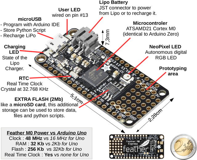
[[fichier:ENG-CANSAT-CONTENT-01.jpg|320px]]
|-
 
| align="center" | '''Feather M0 Features'''
 
|- style="font-size: 90%"
 
| align="left" | 20 GPIOs
 
|- style="font-size: 90%"
 
| align="left" | 6 Analog inputs 12bits<br />value from 0 to 4095.
 
|- style="font-size: 90%"
 
| align="left" | 1 Analog output 10 bits<br />value from 0 to 1023.
 
|- style="font-size: 90%"
 
| align="left" | PWM on all pins
 
|- style="font-size: 90%"
 
| align="left" | Hardware I2C et SPI buses
 
|- style="font-size: 90%"
 
| align="left" | UART
 
|}
 
  
{| class="wikitable" border="1" style="vertical-align: top; display: inline-block;"
+
=== Feather board items ===
|-
 
| align="center" | '''Feather are:'''
 
|- style="font-size: 90%"
 
| align="left" | * Small (5c2xm)
 
|- style="font-size: 90%"
 
| align="left" | * Light (4.7Gr)
 
|- style="font-size: 90%"
 
| align="left" | * Powerful
 
|- style="font-size: 90%"
 
| align="left" | * Versatile
 
|- style="font-size: 90%"
 
| align="left" | * Polyvalent
 
|- style="font-size: 90%"
 
| align="left" | * Available with<br />{{cl|87|complete ecosystem}}
 
|}


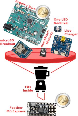
[[fichier:ENG-CANSAT-CONTENT-00.png|640px]]
 
[[fichier:ENG-CANSAT-CONTENT-00.png|640px]]
 +
 +
See the [[ENG-CANSAT-FEATHER-M0-USER-GUIDE|Feather User Guide]] section for more information.
  
 
== Kit content ==
 
== Kit content ==
Ligne 53 : Ligne 26 :
 
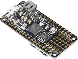
   |descr=New Arduino M0 compatible on a standard platform for embedded project. Also compatible with CircuitPython.
 
   |descr=New Arduino M0 compatible on a standard platform for embedded project. Also compatible with CircuitPython.
 
   |img=FEATHER-M0-EXPRESS.png
 
   |img=FEATHER-M0-EXPRESS.png
   |link=http://shop.mchobby.be/product.php?id_product=1119
+
   |link=https://shop.mchobby.be/product.php?id_product=1119
 
   |qty=1
 
   |qty=1
 
}}
 
}}
Ligne 61 : Ligne 34 :
 
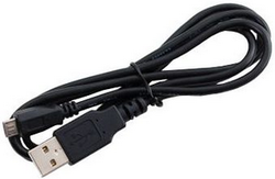
   |descr=Can be used to plug your feather on a computer to program it or to reload the Lipo.
 
   |descr=Can be used to plug your feather on a computer to program it or to reload the Lipo.
 
   |img=CABLE-USB-MICRO.png
 
   |img=CABLE-USB-MICRO.png
   |link=http://shop.mchobby.be/product.php?id_product=145
+
   |link=https://shop.mchobby.be/product.php?id_product=145
 
   |qty=1
 
   |qty=1
 
}}
 
}}
Ligne 69 : Ligne 42 :
 
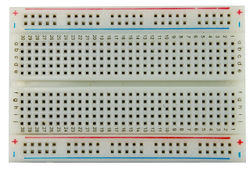
   |descr=Solderless breadboard are used for fast prototyping.
 
   |descr=Solderless breadboard are used for fast prototyping.
 
   |img=BB-DEMI.jpg
 
   |img=BB-DEMI.jpg
   |link=http://shop.mchobby.be/product.php?id_product=53
+
   |link=https://shop.mchobby.be/product.php?id_product=53
 
   |qty=1
 
   |qty=1
 
}}
 
}}
Ligne 77 : Ligne 50 :
 
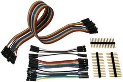
   |descr=Set of wires with plug that can be modified from female to male.
 
   |descr=Set of wires with plug that can be modified from female to male.
 
   |img=FILS-BB-FFASSOR-v2.png
 
   |img=FILS-BB-FFASSOR-v2.png
   |link=http://shop.mchobby.be/product.php?id_product=82
+
   |link=https://shop.mchobby.be/product.php?id_product=82
 
   |qty=1
 
   |qty=1
 
}}
 
}}
Ligne 85 : Ligne 58 :
 
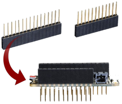
   |descr=Plug your feather or prototype wing on breadboard and still having a female connector under the hand.
 
   |descr=Plug your feather or prototype wing on breadboard and still having a female connector under the hand.
 
   |img=FEATHER-STACK-HEAD.png
 
   |img=FEATHER-STACK-HEAD.png
   |link=http://shop.mchobby.be/product.php?id_product=832
+
   |link=https://shop.mchobby.be/product.php?id_product=832
 
   |qty=1
 
   |qty=1
 
}}
 
}}
Ligne 93 : Ligne 66 :
 
   |descr=Prototyping board for feather platform. Create your own extension board (wing) by soldering connectors and components.
 
   |descr=Prototyping board for feather platform. Create your own extension board (wing) by soldering connectors and components.
 
   |img=FEATHER-PROTO-WING.png
 
   |img=FEATHER-PROTO-WING.png
   |link=http://shop.mchobby.be/product.php?id_product=861
+
   |link=https://shop.mchobby.be/product.php?id_product=861
 
   |qty=1
 
   |qty=1
 
}}
 
}}
Ligne 101 : Ligne 74 :
 
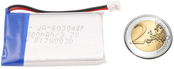
   |descr=Transform the Feather into an autonomous plateform with this 800mAh Lipo.
 
   |descr=Transform the Feather into an autonomous plateform with this 800mAh Lipo.
 
   |img=ACC-LIPO-800mAh.png
 
   |img=ACC-LIPO-800mAh.png
   |link=http://shop.mchobby.be/product.php?id_product=1302
+
   |link=https://shop.mchobby.be/product.php?id_product=1302
 
   |qty=1
 
   |qty=1
 
}}
 
}}
Ligne 109 : Ligne 82 :
 
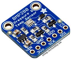
   |descr=Easily evaluate pressure, altitude and temperature.
 
   |descr=Easily evaluate pressure, altitude and temperature.
 
   |img=BMP280.jpg
 
   |img=BMP280.jpg
   |link=http://shop.mchobby.be/product.php?id_product=1118
+
   |link=https://shop.mchobby.be/product.php?id_product=1118
 
   |qty=1
 
   |qty=1
 
}}
 
}}
Ligne 117 : Ligne 90 :
 
   |descr=Transform the sensor voltage read on analog input into an easy-to-read temperature.
 
   |descr=Transform the sensor voltage read on analog input into an easy-to-read temperature.
 
   |img=TMP36.jpg
 
   |img=TMP36.jpg
   |link=http://shop.mchobby.be/product.php?id_product=82
+
   |link=https://shop.mchobby.be/product.php?id_product=82
 
   |qty=1
 
   |qty=1
 
}}
 
}}
Ligne 125 : Ligne 98 :
 
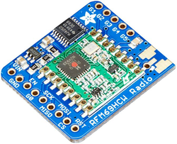
   |descr=Transport data over long distance with packet radio. One breakout act as emitter, the second one as receiver.
 
   |descr=Transport data over long distance with packet radio. One breakout act as emitter, the second one as receiver.
 
   |img=RFM69HCW-433Mhz-BRK.png
 
   |img=RFM69HCW-433Mhz-BRK.png
   |link=http://shop.mchobby.be/product.php?id_product=1390
+
   |link=https://shop.mchobby.be/product.php?id_product=1390
 
   |qty=2
 
   |qty=2
 
}}
 
}}
Ligne 131 : Ligne 104 :
 
{{parts-end}}
 
{{parts-end}}
  
== Feather M0 Express in details ==
 
The Feather M0 use the ATSAMD21G18 ARM Cortex M0+ processor with 3.3V logic and 48 MHz. This chip embed 256K of FLASH (8x more than the Atmega328/Uno) and has 32K RAM (16x more than UNO)!
 
 
This ATSAMD21G18 has USB built-in which offers USB-to-Serial and debug feature (so no need for FTDI-like chip).
 
 
The feather has the following specs:
 
* Size: 51mm x 23mm x 8mm
 
* Weight: 5 grams
 
* ATSAMD21G18 @ 48MHz
 
* 3.3V logic/power
 
* 256KB of FLASH
 
* 32KB of RAM
 
* No EEPROM
 
* RTC & Clock based on 32.768 KHz crystal
 
* 3.3V regulator (500mA peak current) with Power/enable pin
 
* USB native support (has USB bootloader)
 
* 20 GPIO pins (PWM on all pins)
 
* Hardware Serial + Hardware I2C + Hardware SPI support
 
* 6 x 12-bit analog inputs (from 0 to 4095)
 
* 1 x DAC 10-bit analog ouput (from 0 to 1024)
 
* Lipo Charger included: 100mA charging with status LED
 
* Red LED attached on pin #13 (like Arduino UNO)
 
* Reset button
 
* Mini NeoPixel
 
* 2 MB SPI additional Flash storage.
 
 
<div style="margin: 15px 0; background: rgba(255,204,102,.3); display: block; padding: 15px 15px 15px 15px; -webkit-border-radius: 2px; -moz-border-radius: 2px; border-radius: 2px; border: 1px solid #ff9900;" >The Feather M0 Express can be be programmed with Arduino IDE -OR- with CircuitPython (a flavor of MicroPython).
 
 
This tutorial focus on Arduino IDE development. Check the [https://learn.adafruit.com/adafruit-feather-m0-express-designed-for-circuit-python-circuitpython/what-is-circuitpython Adafruit Tutorial if you are interested in '''CircuitPython Programming'''].</div>
 
 
{{underline|'''About the additionnal Flash:'''}}<br />
 
The SPI Flash storage act like a tiny hard drive.
 
* Under CircuitPython, the 2 MB Flash is used to the Python scripts, libraries and other files.
 
* With Arduino, the 2 MB Flash is used to read/write files to it (like a SD card). Adafruit has helper program to access those files over USB.
 
 
{{underline|'''The UF2 bootloader:'''}}<br />
 
The Feather M0 is pre-loaded with an UF2 bootloader which looks like a USB Flash Drive. Simply drag an UF2 firmware on the USB Flash drive to completely reprogram de board firmware (No special tools, No special drivers needed)! The UF2 bootloader can be used to load up CircuitPython, MakeCode PXT file or Arduino IDE (bossa-compatible).
 
 
== Feather M0 Express PINOUT ==
 
=== Introduction ===
 
{{ADFImage|FEATHER-M0-EXPRESS-Brochage-01.png|640px}}<small><br />Click to enlarge</small>
 
 
''(Please note that AREF is PA03 (and not PA02)''
 
 
{{ADFImage|FEATHER-M0-EXPRESS-Brochage-02.jpg|640px}}
 
 
The Feather M0 benefits from the Cortex M0 microcontroler hardware. If has many buses and many pins. Let's review them togheter!
 
 
=== Power Pin ===
 
{{ADFImage|FEATHER-M0-EXPRESS-Brochage-03.jpg|640px}}
 
 
* '''GND ''' : is the common ground. The 0v reference voltage for all the logic and power supplies.
 
* '''BAT''' : positive pin from the JST connector (the optional Lipo).
 
* '''USB ''' : positive pin from the USB connector. Will allow you to detect if the board is connected on USB.
 
* '''EN''' : ''Enable'' pin of the 3.3V regulator. This pin has a Pull-Up résistor. Connect the '''EN''' pin to the ground will shutdown the 3.3V regulator.
 
* '''3V''' : Output of the 3.3V regulator (500mA peak)
 
 
=== Logical pins ===
 
{{ADFImage|FEATHER-M0-EXPRESS-Brochage-04.jpg|640px}}
 
 
This concerns all the I/O pins on the microcontroler.
 
 
<div style="margin: 15px 0; background: rgba(204,14,14,.3); display: block; padding: 15px 15px 15px 15px; -webkit-border-radius: 2px; -moz-border-radius: 2px; border-radius: 2px; border: 1px solid #CCC;" >'''All PINS are 3.3V Logic'''</div>
 
* '''Almost all pins can generate PWM signal''' (also called "''analog output''" on Arduino UNO board).
 
* '''All pins can be used for Interrupt Request (IRQ).'''
 
 
The following pins have specific features:
 
* '''#0 / RX''' - GPIO #0, also receiving pin of the '''Serial1''' UART (hardware ''serial port'', input). Also an analog input.
 
* '''#1 / TX''' - GPIO #1, also transmitting pins of the '''Serial1''' UART (hardware ''serial port'', output). Also an analog input.
 
* '''SDA '''- Data pin for the I2C bus. There is no pull-up resistor on that pin, so you need to add a 2.2K-10K pull-up when used for I2C bus.
 
* '''SCL '''- Clock pin for the I2C bus. There is no pull-up resistor on that pin, so you need to add a 2.2K-10K pull-up when used for I2C bus.
 
* '''#5''' - GPIO #5
 
* '''#6''' - GPIO #6
 
* '''#9 '''- GPIO #9, also analog input '''A7'''. This analog input is wired on a divider resistor bridge to read the Lipoly battery voltage. As a consequence, the voltage of that pin is fixed to a voltage around ~2V.
 
* '''#10''' - GPIO #10
 
* '''#11''' - GPIO #11
 
* '''#12''' - GPIO #12
 
* '''#13''' - GPIO #13, also connected to the '''red LED''' near if the microUSB située près du connecteur micro USB.
 
* '''A0''' - '''Analog input A0''' and also a real '''Analog output''' since the DAC is wired on this pin (DAC = Digital to Analog Converter). The output voltage can be set with a value between 0 and 3.3V. Unlike the PWM output, this pin is {{underline|a real analog output}}. So you can experiment with signal generator.
 
* '''A1 to A5''' - each pin is an Analog input and also a Digital Input/Output.
 
* '''SCK/MOSI/MISO''' - those are the pins for the hardware SPI bus. The pin can also been used to as Digital Input/Output.
 
 
{{underline|'''About buses:'''}}
 
* The SPI bus can reach really high speed so it is a good idea to preserve it, mostly useful with TFT display requiring high throughput to display the content.
 
* The I2C bus can be shared among several devices (usually sensors). So it is also a good idea to preserve the SDA & SCL pins.
 
 
=== SPI Flash and NeoPixel ===
 
The "Express" product line is designed to also run CircuitPython. To ease the prototyping, Adafruit added 2 additional items on the Feather M0:
 
* a mini NeoPixel LED (NeoPixel are Digital RGB LEDs that can be controled with only one data pin)
 
* a 2 MB additional memory (Flash memory on SPI bus.
 
 
{{ADFImage|FEATHER-M0-EXPRESS-Brochage-05.jpg|640px}}
 
 
The '''NeoPixel''' LED is wired on the #8 (in Arduino), so you can use the [https://learn.adafruit.com/adafruit-neopixel-uberguide/arduino-library-use|NeoPixel library] by configuring a ribbon of only 1 pixel. The NeoPixel is powered with 3.3V but this doesn't impact the color or the brightness.
 
 
==== NeoPixel ====
 
The NeoPixel is also used by the bootloader to inform the user about the bootloader state:
 
* Green : The device has been proprely enumerated over the USB interface.
 
* Red : error with the USB.
 
 
Note: In CircuitPython, the LED is used to mention the running status.
 
 
==== The SPI Flash memory ====
 
The Flash memory is wired on 4 reserved pins. Those pins are not made available as GPIO, so no worries about collision risk when using device on the Feather SPI bus. The SPI Flash memory is wired on a different SPI bus... so no worries.
 
 
<div style="margin: 15px 0; display: block; padding: 15px 15px 15px 15px; -webkit-border-radius: 2px; -moz-border-radius: 2px; border-radius: 2px; border: 1px solid #CCC;" >'''Under Arduino'''
 
 
The Flash pins are:
 
* '''SCK''' = pin #3,
 
* '''MISO''' = pin #2,
 
* '''MOSI''' = pin #4
 
* '''CS''' = pin #38.
 
On the '''Feather M0 Express''' you will be able to access this SPI bus (and the Flash) under the name '''SPI1'''. So the Flash device is totally distinct from the Feather GPIO's.
 
 
When used with Arduino, this SPI Flash memory would allow read/write operations.</div>
 
 
<div style="margin: 15px 0; display: block; padding: 15px 15px 15px 15px; -webkit-border-radius: 2px; -moz-border-radius: 2px; border-radius: 2px; border: 1px solid #CCC;" >'''Under CircuitPython (MicroPython Flavor)'''
 
 
Under CircuitPython, the SPI Flash memory is a native storage for the Python interpreter. The Flash memory does appears as read only for the user code.
 
</div>
 
 
=== Other pins! ===
 
{{ADFImage|FEATHER-M0-EXPRESS-Brochage-06.jpg|640px}}
 
* '''RST''' - "''Reset''" pin. Wire this pin to the ground (GND) to reset the microcontroler and start the bootloader.
 
* '''ARef''' - "Analog Reference" pin used when the microcontroler reads analog voltage. As default behavior, the reference voltage is identical to the logic level (so 3.3V). However, you can use a another analog reference voltage (eg: 1.5V) and inform you software to use the external reference AREF EXTERNE. In such case, the 12bits analog reads (value from 0 to 4095) would cover a voltage range from 0 to 1.5V, so a resolution of 1.5/4095=0.366mV.<br><div style="margin: 15px 0; background: rgba(204,14,14,.3); display: block; padding: 15px 15px 15px 15px; -webkit-border-radius: 2px; -moz-border-radius: 2px; border-radius: 2px; border: 1px solid #CCC;" ><font color="#cc0000">'''The reference voltage can never exceed 3.3v. The analogic pin voltage can never exceed the ARef reference voltage!'''</font></div>
 
 
=== Debug Interface ===
 
{{ADFImage|FEATHER-M0-EXPRESS-Brochage-07.jpg|640px}}
 
 
* '''SWCLK et SWDIO''' - ces pastilles, visibles sous la carte, sont utilisées pour programmer le microcontroleur. Ces pastilles permettent également de connecter un débogueur SWD.
 
 
{{ENG-CANSAT-TRAILER}}
 
{{ENG-CANSAT-TRAILER}}

Version actuelle datée du 22 octobre 2021 à 01:04

Feather M0 Express in few words

The CanSat kit it build around the Adafruit Industries Feather M0 Express plateform.

  • Feather is a new emerging standard -Arduino compatible plaform- for embedded projet.
  • Feather is small, light and already brings lot useful features.
  • Feather M0 is compatible with Arduino M0, so compatible with Arduino IDE.
  • Feather M0 Express also embed FLASH memory that can act like SD Card (Arduino IDE) or USB Stick (CircuitPython)
As Feather M0 is compatible Arduino IDE, everything learned for Arduino Uno can be applied to Feather M0. Just care about voltage, the UNO is 5V Logic and the Feather 3.3V logic.

Feather Board content

ENG-CANSAT-CONTENT-01.jpg

Feather board items

ENG-CANSAT-CONTENT-00.png

See the Feather User Guide section for more information.

Kit content

  Description Quantité
Feather M0 Express
FEATHER-M0-EXPRESS.png
New Arduino M0 compatible on a standard platform for embedded project. Also compatible with CircuitPython.
disponible ici chez MCHobby
1
USB A/microB 1m cable
CABLE-USB-MICRO.png
Can be used to plug your feather on a computer to program it or to reload the Lipo.
disponible ici chez MCHobby
1
Half Size Breadboard
BB-DEMI.jpg
Solderless breadboard are used for fast prototyping.
disponible ici chez MCHobby
1
Multi-functional breadboard wires
FILS-BB-FFASSOR-v2.png
Set of wires with plug that can be modified from female to male.
disponible ici chez MCHobby
1
Feather Stacking Headers
FEATHER-STACK-HEAD.png
Plug your feather or prototype wing on breadboard and still having a female connector under the hand.
disponible ici chez MCHobby
1
Feather Prototyping Wing
FEATHER-PROTO-WING.png
Prototyping board for feather platform. Create your own extension board (wing) by soldering connectors and components.
disponible ici chez MCHobby
1
Lithium Polymer Battery
ACC-LIPO-800mAh.png
Transform the Feather into an autonomous plateform with this 800mAh Lipo.
disponible ici chez MCHobby
1
BMP280 – Barometric pressure sensor
BMP280.jpg
Easily evaluate pressure, altitude and temperature.
disponible ici chez MCHobby
1
TMP36 – analog temperature sensor
TMP36.jpg
Transform the sensor voltage read on analog input into an easy-to-read temperature.
disponible ici chez MCHobby
1
RFM69HCW Transceiver Radio
RFM69HCW-433Mhz-BRK.png
Transport data over long distance with packet radio. One breakout act as emitter, the second one as receiver.
disponible ici chez MCHobby
2

Written by Meurisse D. from MC Hobby - License: CC-SA-BY.