Différences entre versions de « ENG-CANSAT-MISSION1-CAPTURE »
Sauter à la navigation
Sauter à la recherche
| Ligne 65 : | Ligne 65 : | ||
# Testing the radio reception | # Testing the radio reception | ||
# Going autonomous (removing Serial Connexion waiting) + add the Lipo | # Going autonomous (removing Serial Connexion waiting) + add the Lipo | ||
| + | === LED and errors === | ||
| + | x | ||
=== Reading and transmitting data === | === Reading and transmitting data === | ||
This Arduino sketch would: | This Arduino sketch would: | ||
Version du 29 octobre 2018 à 18:04
Introduction
| Before starting this point, we recommand to follow all the sensors testing steps (BMP280 sensor, TMP36 Sensor, RFM69HCW radio and RFM69HCW Testing). It contains all the details about the wiring, install needed libraries and conduct basic testing. |
The following Wiring is used to capture
- Air temperature
- Air pressure
and transmissing the information via the RFM69HCW radio module.
Wiring
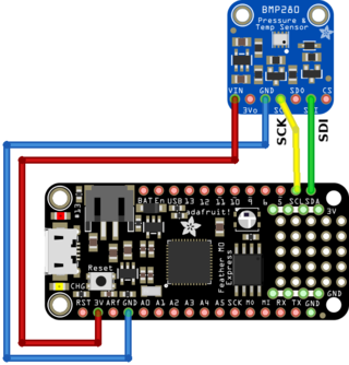
Wire the barometric sensor
The BMP280 is wired on the I2C bus of the Feather.
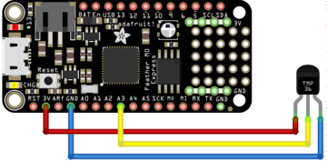
Wire the temperature sensor
Then connect the TMP36 sensor as follows:
- The pin 1 (on the left) to a power source (3.3V),
- The pin 3 (the the right droite) to the ground/GND.
- The pin 2 (middle one) to the A3 analogue input.
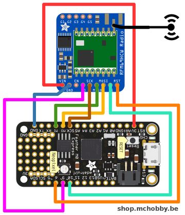
Wire the radio module
Finally wire the RFM69HCW radio as follows:
| Feather M0 Express | RFM69 |
| 3V | VIN |
| GND | GND |
| MO | MOSI |
| MI | MISO |
| SCK | SCK |
| 6 | CS |
| 9 | G0 |
| 10 | RST |
Testing
Now, we will move forward in several steps.
- Getting data from sensors + send them it over the serial connexion (to confirm good working) + transmit over radio
- Testing the radio reception
- Going autonomous (removing Serial Connexion waiting) + add the Lipo
LED and errors
x
Reading and transmitting data
This Arduino sketch would:
- Wait for the serial connexion to be established before starting the sketch
- Collect the sensor data
- Send it to serial connexion
- Send it over the radio connexion
Written by Meurisse D. from MC Hobby - License: CC-SA-BY.


