Différences entre versions de « ENG-CANSAT-MISSION1-CAPTURE »
| Ligne 73 : | Ligne 73 : | ||
The best is to figure out what's happening is to use LED, blink status, heartbeat. | The best is to figure out what's happening is to use LED, blink status, heartbeat. | ||
| − | By doing so, no need to open a Serial Monitor or diagnostic tool to figure out the status of the | + | By doing so, no need to open a Serial Monitor or diagnostic tool to figure out the status of the object. |
| − | [[Fichier:ENG-CANSAT-MISSION1-CAPTURE-10.png| | + | [[Fichier:ENG-CANSAT-MISSION1-CAPTURE-10.png|360px]] |
The NeoPixel LED does turn GREEN when the Feather M0 switch on to normal operation (when it runs your Arduino Sketch). | The NeoPixel LED does turn GREEN when the Feather M0 switch on to normal operation (when it runs your Arduino Sketch). | ||
| Ligne 102 : | Ligne 102 : | ||
|- style="font-size: 90%" | |- style="font-size: 90%" | ||
| align="left" | RADIO LED = 2 pulse 50ms + pause 100ms | | align="left" | RADIO LED = 2 pulse 50ms + pause 100ms | ||
| − | | align="left" | | + | | align="left" | Message send but error while decoding the ACK response. |
| − | | align="left" | | + | | align="left" | ''This is not critical, the most important is that the message was sent successfully''. |
|- style="font-size: 90%" | |- style="font-size: 90%" | ||
| align="left" | RADIO LED = 3 pulse 50ms + pause 150ms | | align="left" | RADIO LED = 3 pulse 50ms + pause 150ms | ||
| − | | align="left" | | + | | align="left" | Not ACK message received within the 500ms after message was sent.<br />This can be interpreted as "Is there someone listening the message?" because there are not reply. |
| − | | align="left" | | + | | align="left" | ''This is not critical, the most important is that the message was sent successfully''. |
|} | |} | ||
Version du 29 octobre 2018 à 20:07
Introduction
| Before starting this point, we recommand to follow all the sensors testing steps (BMP280 sensor, TMP36 Sensor, RFM69HCW radio and RFM69HCW Testing). It contains all the details about the wiring, install needed libraries and conduct basic testing. |
The following Wiring is used to capture
- Air temperature
- Air pressure
and transmissing the information via the RFM69HCW radio module.
Wiring
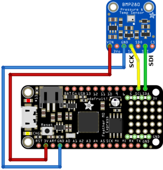
Wire the barometric sensor
The BMP280 is wired on the I2C bus of the Feather.
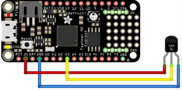
Wire the temperature sensor
Then connect the TMP36 sensor as follows:
- The pin 1 (on the left) to a power source (3.3V),
- The pin 3 (the the right droite) to the ground/GND.
- The pin 2 (middle one) to the A3 analogue input.
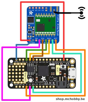
Wire the radio module
Finally wire the RFM69HCW radio as follows:
| Feather M0 Express | RFM69 |
| 3V | VIN |
| GND | GND |
| MO | MOSI |
| MI | MISO |
| SCK | SCK |
| 6 | CS |
| 9 | G0 |
| 10 | RST |
Testing
Now, we will move forward in several steps.
- Getting data from sensors + send them it over the serial connexion (to confirm good working) + transmit over radio
- Testing the radio reception
- Going autonomous (removing Serial Connexion waiting) + add the Lipo
The code proposed here under has been tested up to 22620128 (22.6 millions) iterations without issue, time where we decided to end the test :-) .
LEDs and errors
Being able to understand rapidly what's happening inside your object is essential to fix the issue.
The best is to figure out what's happening is to use LED, blink status, heartbeat.
By doing so, no need to open a Serial Monitor or diagnostic tool to figure out the status of the object.
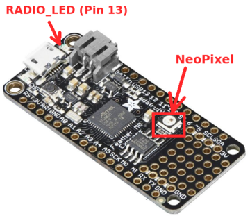
The NeoPixel LED does turn GREEN when the Feather M0 switch on to normal operation (when it runs your Arduino Sketch).
In the following sample, we do take the control over the NeoPixel LED to switch it off at the end of setup() function. This means that all buses and devices are properly initialized.
The RADIO_LED wired on the Pin 13 is used to signal radio status when emitting a message.
| LED operation | Description | Fix the issue |
| NeoPixel GREEN | The setup() function did not complete initialization because of a crash. | Check the wiring of sensors. Test each sensor separately (with their tests code). If this not working, remove all sensors except the one you are testing. |
| NeoPixel OFF | The setup() did complete successfully. The main loop() is not running. | Nothing to do here, just check the RADIO_LED for more informations. |
| RADIO LED = 1 pulse 50ms | The LED is pulsed for each successfully send message + getting ACK from the receiver. The code wait 500ms max for the ACK. | Nothing to do here. |
| RADIO LED = 2 pulse 50ms + pause 100ms | Message send but error while decoding the ACK response. | This is not critical, the most important is that the message was sent successfully. |
| RADIO LED = 3 pulse 50ms + pause 150ms | Not ACK message received within the 500ms after message was sent. This can be interpreted as "Is there someone listening the message?" because there are not reply. |
This is not critical, the most important is that the message was sent successfully. |
Reading and transmitting data
This Arduino sketch would:
- Wait for the serial connexion to be established before starting the sketch
- Collect the sensor data
- Send it to serial connexion
- Send it over the radio connexion
Written by Meurisse D. from MC Hobby - License: CC-SA-BY.


