Différences entre versions de « ENG-CANSAT-MISSION1-RECEIVE »
| Ligne 54 : | Ligne 54 : | ||
Where we could see the received messages with additional information. | Where we could see the received messages with additional information. | ||
| − | <nowiki>[DATA](len=<data_len>,RSSI=<radio_rssi>)< | + | <nowiki>[DATA](len=<data_len>,RSSI=<radio_rssi>)<DATA></nowiki> |
* Each data received and send to the serial connexion are prefixed with '''[DATA]''' | * Each data received and send to the serial connexion are prefixed with '''[DATA]''' | ||
| Ligne 63 : | Ligne 63 : | ||
* '''len''': len of the data. | * '''len''': len of the data. | ||
* '''RSSI''': indicated the [https://en.wikipedia.org/wiki/Received_signal_strength_indication strength of the signal] (-15 at best, -90 at worst). | * '''RSSI''': indicated the [https://en.wikipedia.org/wiki/Received_signal_strength_indication strength of the signal] (-15 at best, -90 at worst). | ||
| + | * '''DATA''': the data as transmitted by the emitter. As designed in the emitter, it starts with ''':''' and ends with ''';\r\n''' | ||
== The code explained == | == The code explained == | ||
Version du 30 octobre 2018 à 16:55
|
|
En cours de traduction/élaboration. |
Introduction
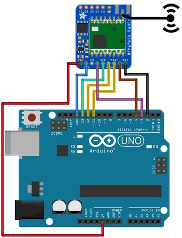
The following wiring will prepare the "Receiver Station" for the mission 1. From the "RFM69HCW Testing" section, we will use an Arduino UNO and RFM69HCW module to redirect the Radio Messages to the serial port.
Wiring
| Feather M0 Express | RFM69 |
| 5V | VIN |
| GND | GND |
| 11 | MOSI |
| 12 | MISO |
| 13 | SCK |
| 4 | CS |
| 3 | G0 |
| 2 | RST |
Download the code
The code is available for download on the GitHub associated to this wiki.
About testing
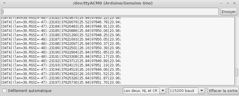
Once uploaded to your Arduino, open the Serial Monitor and set it to 115200 bauds.
You should see the following messages appears on the Serial Monitor.
Where we could see the received messages with additional information.
[DATA](len=<data_len>,RSSI=<radio_rssi>)<DATA>
- Each data received and send to the serial connexion are prefixed with [DATA]
- The prefix is followed by information enclosed between parenthesis (), this concerns the received data.
Entries are key=value pairs separated by coma. - At the end, we retrieve the transmitted data (as they have been sent).
In the informations:
- len: len of the data.
- RSSI: indicated the strength of the signal (-15 at best, -90 at worst).
- DATA: the data as transmitted by the emitter. As designed in the emitter, it starts with : and ends with ;\r\n
The code explained
Here some explanation about the mission1-serial-radio-receiver.ino sketch used in the CanSat.
This Arduino sketch would:
- Collect the sensor data over the radio connexion
- Reply an ACK to the Emitter
- Send it the data to the serial connexion
First, the script will includes all the needed libraries.
Compile and upload
Select the proper board in the menu Tools -> Type of board : Arduino/Genuino UNO
Select the proper port in the menu Tools -> Port
Then press the "compile" button.
Written by Meurisse D. from MC Hobby - License: CC-SA-BY.

