ENG-CANSAT-PICO-RFM69HCW-TEST
Forewords
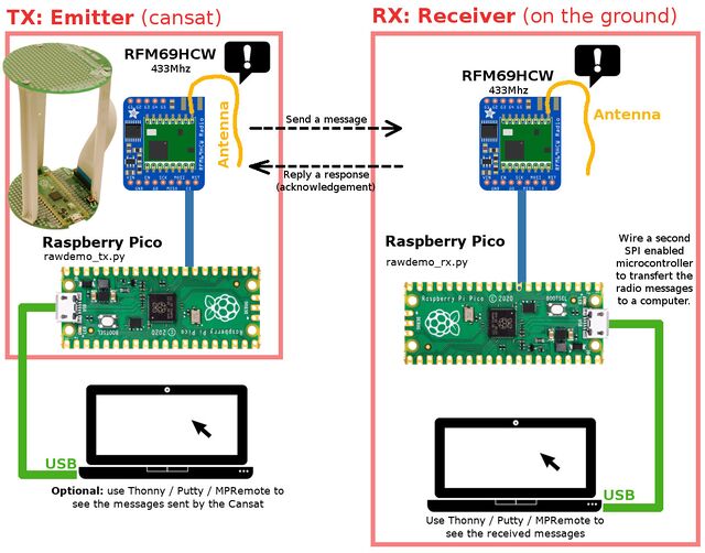
It is now time to establish a communication between:
- a Data Emitter (CanSat) made with a raspberry-Pico + RFM69HCW-433MHz.
- a Data Receiver (Base Station) made with the second RFM69HCW coupled to another Pico microcontroler.
As the kit contains contains two Pico microcontroller we will be able to create the "Data Emitter" on the CanSat as well as the Data Receiver at the ground station.
As we will see, there are 3 key items to be highlighted:
- The frequency must be identical in the emitter and the receiver (eg: 433.1 MHz in this example).
- The encryption key must be identical on the both side.
- Node_IDs used to allow ACK exchange between nodes
In this simple example:
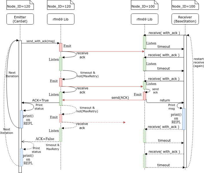
- The Data Emitter (CanSat) will send a message and wait 500ms for a response (ACK).
- The Data Receiver (BaseStation) will receive the message.
- The Data Receiver (BaseStation) will send a ACK reply.
The following sequence diagram (click to enlarge) shows how the calls takes place within scripts, within the library and within the air.
Installing the RFM69 library
The Adafruit's FRM69HCW are provided with a MicroPython library available on GitHub.
You can download and copy the library manually to your board from the Repository.
First, open the repository, then navigate to the file lib/rfm69.py .
Follow the steps describes in the "BMP280 library installation" to copy the RFM69 library to your micropython board.
Once copied, you can also check the proper installation by typing from rfm69 import * .
The RFM69 library repository contains many examples of usage. Do not hesitate to check them!
About Antennas
| The RFM69HCW will not work without antenna, even at 1m distance of each other. |
For this example, a simple wire twisted in the antenna hole will do a great job for testing.
Please wait before soldering the wire inside the antenna hole!. The antenna hole can be populated with:
- a simple wire
- a µFl SMT antenna connector where you could plug various kind of antenna.
- a PCB SMA Connector where you could plus various kind of antenna.
A µFl connector (also named uFl) is looking to this:
A PCB SMA Connector is looking to this:
Frequency, Encryption & Power
To make the module communicating together:
- The module must be identical. You cannot mix them.
- The tuned frequency must be identical.
- The encryption key must be identical.
Tuned frequency
The tuned frequency is declared with a line like this:
...
rfm = RFM69( spi=spi, nss=nss, reset=rst )
rfm.frequency_mhz = 433.1
where the tuned frequency is directly assigned to the frequency_mhz property.
| Use the frequency assigned to your team by the instructor. |
In packet radio, several teams can share the same frequency if they use distinct encryption key.
Like TCP (from TCP/IP network), the packet radio is able to detect packet collision and try to recover from it.
However, more teams share the same frequency, more collision we have.
Encyption Key
The module encrypts the data with AES-128.
The encryption key is defined with 16 bytes and assigned to the encryption_key property.
The code here below defines the key 1234567812345678 under binary format.
...
rfm = RFM69( spi=spi, nss=nss, reset=rst )
rfm.encryption_key = (  b"\x01\x02\x03\x04\x05\x06\x07\x08\x01\x02\x03\x04\x05\x06\x07\x08" )
It is also possible to defines the same key with a more user friendly code.
...
rfm = RFM69( spi=spi, nss=nss, reset=rst )
rfm.encryption_key = bytes( [1,2,3,4,5,6,7,8,1,2,3,4,5,6,7,8] )
| It is highly recommended for each team to define its own encryption key. |
When all the teams do use the same frequency and the same key then they will all receives the messages from the other teams also sending messages. Your messages will also been received by all the other teams.
Transmission Power
The transmission power is set to 13 dBm by default (it is safer across all RFM modules, the library also work for RFM95).
The transmission power can be set from 14 to 20 dBm by assigning the tx_power property.
Lowest values requires less power. Less power means higher battery life but also smaller transmission distance.
rfm = RFM69( spi=spi, nss=nss, reset=rst )
# rfm.tx_power = 13  # 13 dBm = 20mW (default value, safer for all modules)
rfm.tx_power = 20 # 20 dBm = 100mW, 20 dBm for FRM69HW only
Tips & Tricks:
It is possible to estimate the transmission power (in milliWatts) by using the following function.
def dbm_to_mw(dBm):
	""" Transform the power in dBm to its equivalent in milliWatt """
	return 10**((dBm)/10.)
Check the wiring
Before showing the details of the wiring diagrams, here is a "tip" helping to check it!
The following script "test-rfm69/test_config.py" (TODO TODO TODO TODO) from the cansat-belgium-micropython contact the RFM69 module to initialize it and read back properties.
If the script can properly establish a communication with the module, it will returns the following results:
RFM version     : 36
Freq            : 433.1
Freq. deviation : 250000.0 Hz
bitrate         : 250000.0 bits/sec
tx power        : 13 dBm
tx power        : 19.95262 mW
Temperature     : 23 Celsius
Sync on         : yes
Sync size       : 1
Sync Word Length: 2 (Sync size+1)
Sync Word       : bytearray(b'-\xd4')
crc on          : 1
Preamble Lenght : 4
aes on          : 1
Encryption Key  : bytearray(b'\x01\x02\x03\x04\x05\x06\x07\x08\x01\x02\x03\x04\x05\x06\x07\x08')
The Receiver (BaseStation)
We will prepare our receiver station.
The receiver stays on the ground and receives the message sent by the Emitter and forward them to a computer.
This will involve:
- The second RFM69HCW 433 Mhz module
- A Pico microcontroler
- A computer to read the messages (forwared by the microcontroler)
- An wire antenna
Receiver Wiring
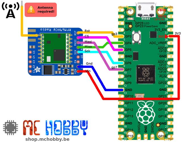
Here how to wire the RFM69 module to the Raspberry-Pi Pico.
Here is the description of wiring between the Pico and the RFM69 module.
| RFM69HCW | PICO |
|---|---|
| RST |
GP3 |
| CS | GP5 (Slave Select) |
| MOSI | GP7 (Mosi) |
| MISO | GP4 (Miso) |
| SCK | GP6 (Clock) |
| GND | GND |
| VIN | 3V3 |
Receiver code
Now we will load and executes the test_receiver.py receiver script. The script must be downloaded from the repository.
The script can be either executed from Thonny -OR- transfered to the Pico and executed directly on the microcontroler.
It will output the messages on the REPL/Shell over the serial line.
| We will have to modify the script before executing it! |
The frequency and encryption key must be updated from team to team to avoids messages collisions and cross-over transmission between the teams.
As the organisator for your team frequency according to the Frequency Plan
Update for frequency plan, encryption key:
- The frequency used by the receiver RFM69HCW must be exactly the same as the emitter!
- The Encryption key used by the receiver RFM69HCW must be exactly the same as the emitter!
- The Node ID is the unique node id (0..255) where the emitters will sent the messages.
Locate the following lines:
FREQ           = 433.1
ENCRYPTION_KEY = b"\x01\x02\x03\x04\x05\x06\x07\x08\x01\x02\x03\x04\x05\x06\x07\x08"
NODE_ID        = 100 # ID of this node
And update the value for FREQ and ENCRYPTION_KEY.
The NODE_ID doesn't have to be updated, its is used as node identifier allowing message & ACK exchange between one receiver and several emitter (each having an unique NODE_ID (for the same ENCRYPTION_KEY and FREQ).
Receiver test
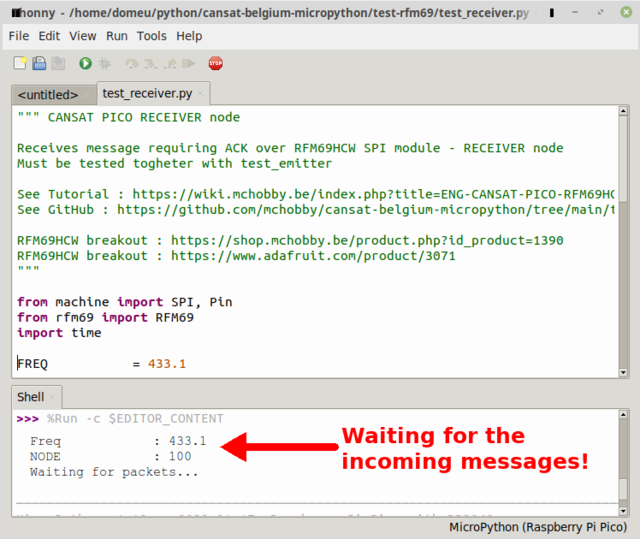
Openning the Serial Line and run the receiver_test.py script.
As we want to see the received message, we will open a terminal to receives the messages over the USB-Serial line.
This can be done with the help of:
- Thonny IDE (that will automatically open the USB-Serial port)
- Putty (just open the USB-Serial port)
- mpremote
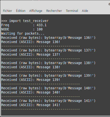
Just starts the script and wait for the messages to come:
Voilà, we are ready to test the emitter (cansat).
In this second screen capture (here below), we do used the "mpremote" (command line tools) to access the REPL/Shell session on the Pico board.
| WHEN the file test_receiver.py is copied to the micropython board THEN it can be started from REPL with import test_receiver |
As we can see on the screen capture, the script is receiving messages from emitter and sending ACK back to the sender.
As the first message received is numbered 136, we do know for sure that the emitter script was started a while before.
The Emitter (CanSat)
The emitter can be made 2 different ways (shown below).
The wiring is, in facts, identical in the two options (and identical to receiver).
Only the script content will changes between the emitter and the receiver.
Emitter Wiring 1 : as the receiver
wiring (visible here before) is identical to the receiver wiring.
(see the Receiver section for more details about the connections).
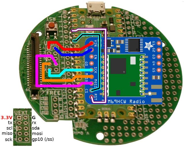
Emitter Wiring 2: with the Kit Cansat for Pico
Kit Cansat avec Raspberry-Pi Pico have a Raspberry-Pi Pico soldered onboard. The RFM69 module can be soldered on the UEXT connection points available between the Pico and the Ribbon connector.
| The RFM69HCW radio module can be soldered above or below the base board (depending on your needs). |
UEXT can manage almost all the signals, only RST and SS must be soldered directly on the Pico GPIOs pins. For sure, if you want to solder all the connection directly to the Pico GPIO, you can also do the connection that way.
Here how to wire the RFM69 module to the base board of Cansat Kit with Pico as recommended.
| 22/11/2022 21:23 - fix the wiring miso-->miso & mosi-->mosi in the diagram. |
| RFM69HCW | UEXT pin | PICO | Remark |
|---|---|---|---|
| RST | GP3 | ||
| CS | GP5 | keep the same pin as receiver. Otherwise use UEXT 10 (=gp10) | |
| MISO | 7 | GP4 = MISO | |
| MOSI | 8 | GP7 = MOSI | |
| SCK | 9 | GP6 = SCK | |
| GND | 2 | PICO GND | |
| VIN | 1 | PICO 3.3V |
| The "Slave Select" line on the UEXT connector is not used in this setup because it is wired to PICO GP10. As we want the RFM69 setup code to be the same between the emitter and the receiver... we do need to wire the RFM69's CS line to GP5. |
Emitter code
Now we will load and executes the test_emitter.py emitter script for the CanSat.
The script must be downloaded from the repository.
The script can be either executed from Thonny -OR- transfered to the Pico and executed directly on the microcontroler.
It will output the messages on the REPL/Shell over the serial line.
| We will have to modify the script before executing it! |
The frequency and encryption key must be updated from team to team to avoids messages collisions and cross-over transmission between the teams.
Ask the organizer for your team frequency according to the Frequency Plan
Update for frequency plan, encryption key:
- The frequency used by the receiver RFM69HCW must be exactly the same as the emitter!
- The Encryption key used by the receiver RFM69HCW must be exactly the same as the emitter!
Locate the following lines:
FREQ           = 433.1
ENCRYPTION_KEY = b"\x01\x02\x03\x04\x05\x06\x07\x08\x01\x02\x03\x04\x05\x06\x07\x08"
And update the value for FREQ and ENCRYPTION_KEY.
Update BaseStation ID:
- The Node ID is unique node identifier (0..255). This also the node ID where the base station (the receiver) must send the ACK the response.
- The BaseStation ID the node id (0..255) where the CanSat emitter must sent the messages (and from which the ACK response are expected).
The NODE_ID and BASESTATION_ID are preconfigured and doesn't need to be updated.
Remark: the frequency & encryption key are enough to "isolate a group". Nodes ID are used to create mesh network within a group. A simple mesh with 2 nodes (the Receiver base station and the Emitter CanSat) is enough to exchange messages with Acknowledgement.
Anyway Node ID can be updated for test purpose. To do so, locate the following lines:
NODE_ID        = 120 # ID of this node
BASESTATION_ID = 100 # ID of the node (base station) to be contacted
Emitter test
Opens the Serial Line and run the emitter_test.py script.
As we want to see the sent messages and acknowledgments, we will open a terminal to receives the messages over the USB-Serial line.
This can be done with the help of:
- Thonny IDE (that will automatically open the USB-Serial port)
- Putty (just open the USB-Serial port)
- mpremote
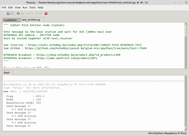
Just starts the script it will start to send messages (as the CanSat will do) to the base station and waits for the ACK notification from the base station:
As the base station (receiver_test.py) is not running now ACKnowledgment are sent to the emitter.
| WHEN the file test_emitter.py is copied to the micropython board THEN it can be started from REPL with import test_emitter |
The following capture show the emitter_test.py script running from the Thonny. As seen below the messages are properly received by the receiver (the base station) as it sent back the ACKnowledgment.
Stress Test
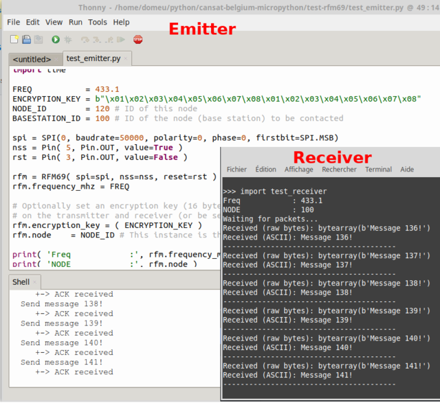
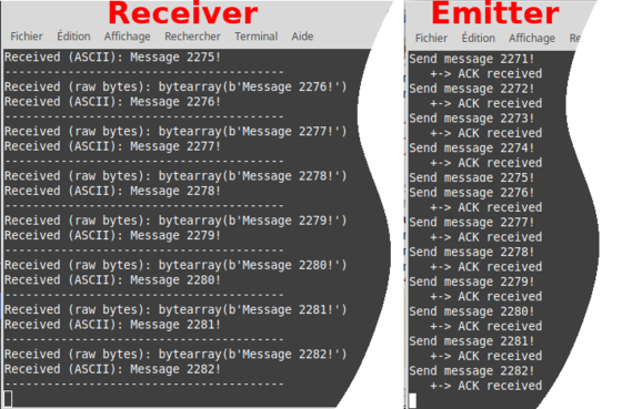
By reducing the emission delay from 1 second between messages to 100ms (0.1sec), it is possible to evaluates the reliability and stability of the communication with ACK.
The following screen capture shows the receiver and emitter captured after 2200+ messages sent and ack.
More info
Understanding script content
Reading the sketch would help to understand how the code works. The scripts contains many comments.
Addressed & Reliable Communication
More complex setup could used addressed communication and Reliable Datagram.
- Addressed communication, used here, allows you to associate a unique identifier (node id, an integer from 0..255) to each RFM69 module. This allows identifies the sender when receiving a message (on the frequency+AES) and to act appropriately properly and possibly send back a response. Addressed mode is suited when building a team of robot!
- Reliable Datagram do a lot of management with connection to make sure that the packets were received. You do not have to send the acknowledgement in your own code, the Reliable Datagram take care of it for you from inside the library.
Check the examples associated the RFM69 library for more informations.
Written by Meurisse D. for MCHobby
