Différences entre versions de « ENG-CANSAT-RFM69HCW »
| (7 versions intermédiaires par le même utilisateur non affichées) | |||
| Ligne 1 : | Ligne 1 : | ||
{{ENG-CANSAT-NAV}} | {{ENG-CANSAT-NAV}} | ||
| − | {{ | + | {{COMMON-CANSAT-RFM69HCW}} |
| − | + | ||
| − | |||
| − | |||
| − | |||
| − | |||
| − | |||
| − | |||
| − | |||
| − | |||
| − | |||
| − | |||
| − | |||
| − | |||
| − | |||
| − | |||
| − | |||
| − | |||
| − | |||
| − | |||
| − | |||
| − | |||
| − | |||
| − | |||
| − | |||
| − | |||
| − | |||
| − | |||
| − | |||
| − | |||
| − | |||
| − | |||
| − | |||
| − | |||
| − | |||
| − | |||
| − | |||
| − | |||
| − | |||
| − | |||
| − | |||
| − | |||
| − | |||
| − | |||
| − | |||
| − | |||
| − | |||
| − | |||
| − | |||
| − | |||
| − | |||
| − | |||
| − | |||
| − | |||
| − | |||
| − | |||
| − | |||
| − | |||
| − | |||
| − | |||
| − | |||
| − | |||
| − | |||
| − | |||
| − | |||
| − | |||
| − | |||
| − | |||
| − | |||
| − | |||
| − | |||
| − | |||
| − | |||
| − | |||
| − | |||
| − | |||
| − | |||
| − | |||
{{ENG-CANSAT-TRAILER}} | {{ENG-CANSAT-TRAILER}} | ||
Version actuelle datée du 27 février 2022 à 03:21
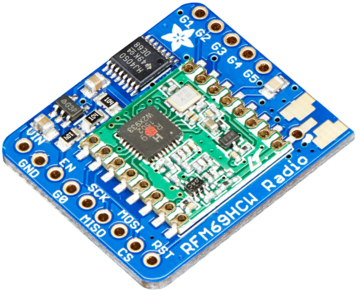
RFM69 Radio Module
Before starting make sure you have your Feather and Arduino working properly with basic functionalities. This will make this part more easier and you can upgrade your project to radio transmission.
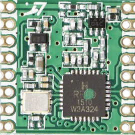
Both RFM69 and RFM9x LoRa breakouts have the exact same pinouts! And they exists in 900 MHz or 433 MHz flavor.
- The silkscreen identify the RFM69HCW -OR- LoRa
- The 900 MHz modules have a green or blue dot on top.
- The 433 Mhz modules have a red dot on top.
The sub-GHz radio transmission does have lower throughput so it is not made to stream audio or video! The sub-GHz is suited for small packets of data. The data rate is adjustable but its common to stick to around 19.2 Kbit per second. Lower is the rate and better woud be the transmissions.
To use such modules you will need both of them! The radios must be matched in frequency (eg: 433 MHz & 433 MHz will match, 433 MHz & 900 MHz will not match).
The both module must use the same encoding schemes. You cannot use a RFM69 900 MHz packet radio together with a RFM9x packet radio (LoRa).
| In Belgium, you cannot use the RFM69 900 Mhz without having the appropriate license, see this "IBTP Frequency Plan" link for more details. |
According to the same "IBTP Frequency Plan" the RFM69HCW should be used between 430-440 MHz.
Raw vs Packet Transmission
The SX1231 module used on the RFM69 breakout board can be used in 'raw Rx/Tx' where it modulates incoming bits (from pin #2) and sends them on the radio. In 'raw Rx/Tx' there is no error correction and no addressing. This mode is weak and error prone so it will not be covered.
Packet mode will be suited for almost 99% of use cases. When packetized, the code can setup a recipient for the data, ensure error correction (data transmitted correctly), automatic retries on transmission error and acknowledgement when the packet is delivered. In packet mode, you got a reliable data pipe, transparent communication without getting care about the complex details of data transmission over radio frequencies.
With a SX1231 module, the complexity is reduced to 4 main characteristics more easy to handle:
- the frequency to use
- the power level to use
- the encryption key to use
- the appropriate antenna (depending on the expected transmission range)
Broadcasting vs Mesh transmitting
What is broadcasting?
Considering everybody using the same frequency and same encryption key are all on the same place:
- Broadcasting is a bit like shout out loud what you have to say on public place.
- Everybody can ear you and the remittee/recipient of the message have to pay attention for the message addressed to him.
- The recipient can reply (by shouting out loud its response). Everybody can also respond in place if the remittee (if he wants too).
- Everyone can speak out loud and multiple talk can disturbs each other!
It can quickly become a cacophony, even in the hertzian area. Broadcasting is not an efficient way to communicates.
When to use broadcasting?
- When the message must be send to anyone (like a "Panic" message).
- When there are max 2 persons/devices involved in the exchange
What is a Mesh network?
Considering everybody using the same frequency and same encryption key are all on the same place:
- Mesh network is like everybody is using a mobile phone to contact the remittee/recipient.
- Everybody has a unique phone number (a NODE_ID) used to contact him.
- The exchange/dialog/conversation is strictly private.
- Several conversations can occurs at the same time without disturbing each other.
- Anyone is still able to received a broadcast message.
| A mesh network is more than that! It can also use an intermediate node to contact a more distant contact. |
When to use mesh network?
- When each person/device in uniquely identified (this is a requirement, identification known as NODE_ID).
- When there is more than two persons/devices sharing the network/area.
- When the information must be privately exchange between 2 persons/devices
- When acknowledgment are suited in the communication.
Indeed, we have to know the number of each other (NODE_ID) to callback for acknowledgement).
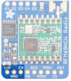
Power Pins
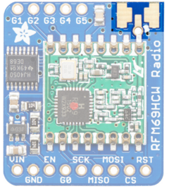
- GND: Common ground between logic and power.
- Vin: Power In 3.3 to 6V. The board regulated it to 3.3V. Be sure you can supply up to 150mA on this pin since Radio Emitting can reach this current level.
- EN: Enbable Pin used to switch off the Power supply (and the radio module). EN pin use a pull-up resistor to maintain the regulator enabled, just set it to LOW to switch off the radio.
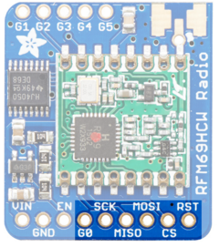
SPI Interface Pins
Those pins are use to communicate with the host micro controller. The standard SPI bus pins are MISO, MOSI, CLK and ChipSelect.
This radio breakout also expose the radio RESET pin and radio INTERRUPT pin (named G0) to offer a better control over the Radio communication.
| All the pins (except extra GPIOs) are wired thought a level shifter. This means that logical level (3.3 or 5V) will be compatible with the voltage applied on Vin! |
- MISO: Master In Slave Out. This pin is used to send data from the radio (the slave) to the micro controller (the master).
- MOSI: Master Out Slave In. This pin is used by the micro controller to send data to the radio.
- SCK: Clock signal used to synchronise bits exchanges between the Master and the Slave.
- CS: This is the Chip Select. Place it to LOW level to initiate transaction with the radio module. The CS pin make sense when several slaves (eg: radio module + LCD display) are present on the SPI bus.
- RST: The reset pin of the radio module. Set it to LOW to reset the radio module.
- G0: This is the GPIO 0 pin of the radio module. This pin has a special interruption function attached to it because it act as IRQ (Interrupt Request) pin. The radio module manipulate it to send to notification toward the micro controller. This pin is in 3.3V logic.
Antenna spot
There are 3 ways to connect an antenna on this spot.
The cheapest is the wire antenna (a simple dipole) and the best option is the SMA connector.
| An antenna is ABSOLUTELY REQUIRED to allow any data transmission. No communication possible (even 1 meter) without antenna. |
For testing purpose, we suggest to twist a wire inside the antenna hole (take care to not touch the ground spots with the wire).
Later on, you would focus on antenna choice:
- A wire inside the antenna hole (said a wire dipole).
- A µFl connector to plug antenna.
- A PCB SMA connector also to plug other kind of antenna.
A µFl connector (also named uFl) is looking to this:
A PCB SMA Connector is looking to this:
Extra GPIOs Pins
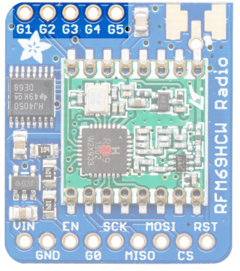
The radio module also feature 5 additionnal GPIOs (from G1 to G5) to raise interrupt request depending specific conditions.
As they are usually free for use (not used for notification or radio functions) you can control them for the purpose of your project.
Those pins are 3.3V logic without level shifting.
Written by Meurisse D. from MC Hobby - License: CC-SA-BY.
