Différences entre versions de « MICROPYTHON-MOD-IO »
| Ligne 20 : | Ligne 20 : | ||
Voyez {{pl|1408|notre fiche produit pour plus d'informations}}, schéma, utilisation OlinuXino, etc. | Voyez {{pl|1408|notre fiche produit pour plus d'informations}}, schéma, utilisation OlinuXino, etc. | ||
| − | == Matériel | + | == Matériel utilisé == |
Pour réaliser ce test, nous avons utilisé: | Pour réaliser ce test, nous avons utilisé: | ||
| Ligne 58 : | Ligne 58 : | ||
{{parts-end}} | {{parts-end}} | ||
| + | |||
| + | == Montage == | ||
| + | Les raccordements sont effectués comme suit: | ||
| + | |||
| + | [[Fichier:MICROPYTHON-MOD-IO-20.png]] | ||
| + | |||
| + | * L'opto-coupleur IN3 est activé à l'aide d'une tension de 16V (choisi arbitrairement entre 5 et 24V DC) | ||
| + | * Un potentiomètre de 10K est branché sur l'entrée analogique 2 (AIN-2) avec une tension fixée à 1.129v | ||
| + | * Les relais 1 et 3 (sur les 4 relais à disposition) sont activés par le code Python. | ||
| + | |||
| + | {{ambox-stop|text=Attention: ne pas appliquer plus de 5V sur la carte d'évaluation ESP8266-EVB}} | ||
== Où acheter == | == Où acheter == | ||
Version du 10 octobre 2018 à 11:12
Introduction
|
|
En cours de traduction/élaboration. |
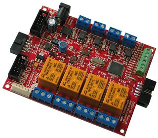
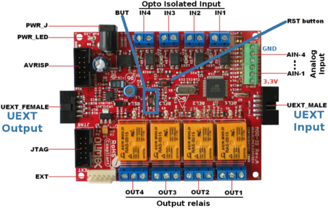
MOD-IO is a stackable development board which adds analog and digital inputs and outputs to any of our development boards with UEXT. If you work with any of our development boards with a UEXT connector and you need more digital and analog inputs and outputs, you can add these by connecting MOD-IO to your development board. This board allows easy interfacing to 4 relays, 4 optoisolated digital inputs, 4 analog inputs. MOD-IO is stackable and addressable, what does this mean? It means that these boards can plug together so that you can add as many inputs and outputs as you want! E.g. 2-4-6-8 etc.! The MOD-IO has an ATmega16 microcontroller and the firmware is available for modification.
It features:
- Open source hardware board with ATmega16L-8AU microcontroller à 8 MHz.
- EXT extension connector
- Status LED
- Reset IC ZM33064 to protect the board againt low voltage running.
- Power plug-in jack, DC-DC with input voltage 8-30VDC (compatible avec les alimentations industrielles 24V)
- 4-optocoupler isolated inputs with screw terminals with Input status LEDs
- 4-relay outputs with 5A/250VAC contacts with screw terminals with Output status LEDs
- Dimensions 80x100 mm
Voyez notre fiche produit pour plus d'informations, schéma, utilisation OlinuXino, etc.
Matériel utilisé
Pour réaliser ce test, nous avons utilisé:
| Description | Quantité | |
ESP8266-EVB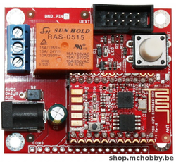
|
ESP8266 Evaluation Board d'Olimex disponible ici chez MCHobby |
1 |
MOD-IO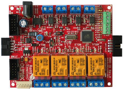
|
Carte MOD-IO d'Olimex disponible ici chez MCHobby |
1 |
UEXT-SPLITTER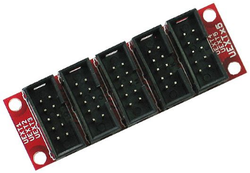
|
Multiplicateur de port UEXT. Permettra de brancher la carte + Interface USB-Serie disponible ici chez MCHobby |
1 |
USB-SERIE-TTL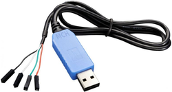
|
Un cable console pour pouvoir communiquer avec l'ESP8266 disponible ici chez MCHobby |
1 |
Montage
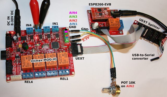
Les raccordements sont effectués comme suit:
- L'opto-coupleur IN3 est activé à l'aide d'une tension de 16V (choisi arbitrairement entre 5 et 24V DC)
- Un potentiomètre de 10K est branché sur l'entrée analogique 2 (AIN-2) avec une tension fixée à 1.129v
- Les relais 1 et 3 (sur les 4 relais à disposition) sont activés par le code Python.
| Attention: ne pas appliquer plus de 5V sur la carte d'évaluation ESP8266-EVB |
Où acheter
- Le ESP8266-EVB utilisé dans ce tutoriel pour faciliter le raccordement. Pourrait fonctionner avec un Feather ESP8266 avec le raccordement adéquat.
- Le ESP8266-DEV module équipant la carte ESP8266-EVB.
- Le module MOD-IO
- Le module UEXT Splitter
- La La gamme IoT/ESP8266 disponible chez MC Hobby
- Un Convertisseur USB-Série TLL
Tutoriel réaliser par Meurisse D. pour MC Hobby SPRL
Toute référence, mention ou extrait de cette traduction doit être explicitement accompagné du texte suivant : « Traduction par MCHobby (www.MCHobby.be) - Vente de kit et composants » avec un lien vers la source (donc cette page) et ce quelque soit le média utilisé.
L'utilisation commercial de la traduction (texte) et/ou réalisation, même partielle, pourrait être soumis à redevance. Dans tous les cas de figures, vous devez également obtenir l'accord du(des) détenteur initial des droits. Celui de MC Hobby s'arrêtant au travail de traduction proprement dit.
