MP6500
Présentation
|
|
En cours de traduction/élaboration. |
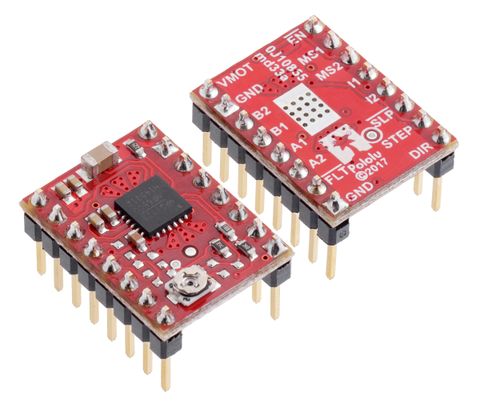
Le MP6500 de la société MPS est capable de contrôler un moteur pas-à-pas bipolaire en pas complet et en micro-stepping.
Le brochage et l'interface sont presque identique au populaire A4988, le MP6500 peut être utilisé comme remplacement du A4988 pour de nombreuses applications. Avec le MP6500 il y a un support micro-stepping jusqu'au 1/8 de pas et il est capable de supporter une tension moteur de 4.5 V à 35 V avec un courant constant de ~1.5 A par phase (2.5 A en pointe).
La carte est équipée d'un limiteur de courant que peut être réglé à l'aide du potentiomètre présent sur la carte.
| D'autres contrôleurs comme le A4988 supporte le micro-stepping jusqu'au 1/16 de pas, plus approprié pour l'impression 3D. |
Micro-stepping? Kaseko?!?!
Le micro-stepping permet de diviser un pas en plusieurs micro-pas... offrant une plus grande granularité pour effectuer une révolution d'axe.
Sans micro-stepping un moteur 200 a uniquement besoin de 200 pas (impulsions sur STEP) pour faire une révolution complète de l'axe. Soit 1.8° par pas.
Avec un micro-stepping 1/8 pas, les bobines du moteur sont contrôlées de tel sorte qu'il faudra alors 200*8 = 1600 pas (soit 1600 impulsions sur STEP) pour effectuer une révolution complète de l'axe. Soit 0.225° par pas.
A propos du limiteur de courant
Le contrôleur moteur MP6500 dispose d'un limiteur de courant. Ce dispositif contrôle activement le courant envoyé vers les bobines et empêche celui-ci de dépasser une consigne fixée à l'aide du potentiomètre.
Sans limiteur de courant, le courant traversant une bobine dépend de la tension qui y est appliqué. Sur une bobine avec une impédance de 30 Ohms et tension max 9V et courant max 0.300mA (cette mention est importante). La règle U = R x I permet de vérifier que la tension max = 30 Ohms * 0.300mA = 9V.
En première approximation, la puissance dissipée est P=R*I^2 (proportionnel au carré du courant). Soit 30x0.300^2 = 2.7 Watt. Cette puissance dissipé, c'est ce qui provoque l'échauffement et grille/brûle les bobines si elle devient trop importante.
C'est cette dissipation de puissance qui empêche d'augmenter la tension.
A titre d'exemple, si la tension est augmentée à 12V, le courant dans les bobines passe à 12V / 30 Ohms = 0.4 A (soit 400mA). Avec 400mA, la puissance dissipée passe à P=R*i^2 = 30 * 0.4^2 = 4.8 Watt, ce qui provoquera un échauffement excessif (et à terme la défaillance du moteur).
Avec limiteur de courant, le courant traversant la bobine sera activement contrôlé pour ne pas dépasser la consigne fixée. Cela importe peu si l'on alimente le moteur en 9V comme recommandé. Par contre, alimenté en 12V, le courant reste activement limité à 150mA et comme la tension est plus élevée, le champs magnétique dans le moteur sera plus important, ce qui rend ce dernier plus réactif. Grâce à un limiteur de courant, il est possible de travailler en surtension sans griller le moteur, ce qui permet d'atteindre des vitesses de rotation plus élevées.
Détails techniques
- Interface de commande super simple. Utilise une broche STEP et une broche DIRECTION (sens de rotation)
- 4 résolutions de pas:
- Pas simple (full-step),
- Demi-pas (half-step),
- 1/4 de pas (1/4-step),
- 1/8 de pas (1/8-step)
- Limiteur de courant
- Deux contrôles de limitation de courant disponible:
- La présente version contient un contrôle de courant par potentiomètre — le potentiomètre présent sur la carte permet de limiter le courant à 2.5 A
- Il existe également une version de ce breakout avec un Contrôle Digital du Courant (disponible sur demande) — cette autre version permet au microcontrôleur d'ajuster dynamiquement la limite du courant (jusqu'à 2 A)
- Un senseur de courant interne permettant au contrôleur d'ajuster automatique la mode décroissance de sortie à fournir une onde de courant lissée.
- Tension moteur de 4.5 V à 35 V
- Soutient un continuellement un courant de 1.5 A par phase (sans refroidissement supplémentaire)
- Courant de pointe de 2.5 A
- Régulateur de tension intégré (pas besoin d'un tension séparée pour la logique de contrôle)
- Compatible systèmes 3.3 V et 5 V.
- Protection:
- arrêt lors de surchauffe,
- arrêt lors de sur-courant,
- protection contre court-circuit,
- blocage lors de sous-tension
- Carte constitué de 4 couches permettant d'améliorer la dissipation de chaleur
- Pastille de masse (soudable) exposée sous le circuit intégré du contrôleur.
- Fiche technique du MP6500 (pdf, 1 Mb)
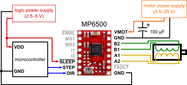
Raccordements
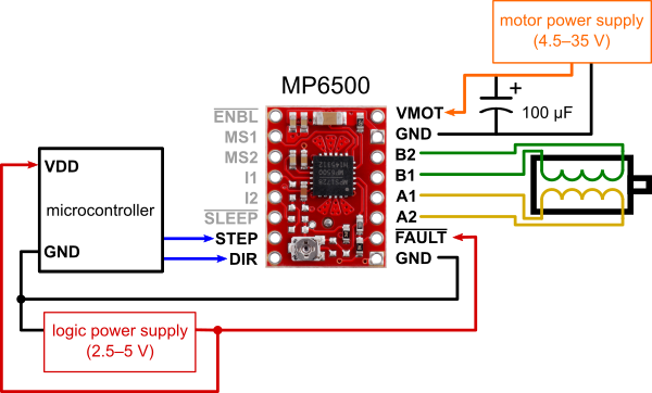
Montage alternatif:
Alimentation
|
|
En cours de traduction/élaboration. |
The driver requires a motor supply voltage of 4.5 V to 35 V to be connected across VMOT and GND. This supply should have appropriate decoupling capacitors close to the board, and it should be capable of delivering the expected stepper motor current. The driver has an internal voltage regulator, so it does not require a logic voltage supply.
| This carrier board uses low-ESR ceramic capacitors, which makes it susceptible to destructive LC voltage spikes, especially when using power leads longer than a few inches. Under the right conditions, these spikes can exceed the 40 V absolute maximum voltage rating for the MP6500 and permanently damage the board, even when the motor supply voltage is as low as 12 V. One way to protect the driver from such spikes is to put a large (at least 47 µF) electrolytic capacitor across motor power (VMOT) and ground somewhere close to the board. |
Connexion moteur
Four, six, and eight-wire stepper motors can be driven by the MP6500 if they are properly connected; a FAQ answer (Pololu, anglais) explains the proper wirings in detail.
| Warning: Connecting or disconnecting a stepper motor while the driver is powered can destroy the driver. (More generally, rewiring anything while it is powered is asking for trouble.) |
Vitesse et Micro-stepping
Warning: Connecting or disconnecting a stepper motor while the driver is powered can destroy the driver. (More generally, rewiring anything while it is powered is asking for trouble.)
| MS1 | MS2 | Résolution Microstep |
| bas | bas | Full step (Pas complet) |
| haut | bas | Half-step (Demi pas, 1/2) |
| bas | haut | Quarter-step (Quart de pas, 1/4) |
| high | high | Heighth-step (huitième de pas, 1/8) |
Entrées de contrôle
Each pulse to the STEP input corresponds to one microstep of the stepper motor in the direction selected by the DIR pin. These inputs are both pulled low by default through internal 500 kΩ pull-down resistors. If you just want rotation in a single direction, you can leave DIR disconnected.
The chip has two different inputs for controlling its power states: SLEEP and ENBL. For details about these power states, see the datasheet. Please note that the driver pulls both of these pins low through internal 500 kΩ pull-down resistors. The default SLEEP state prevents the driver from operating; this pin must be high to enable the driver (it can be connected directly to a logic “high” voltage between 2.5 V and 5 V, or it can be dynamically controlled by connecting it to a digital output of an MCU). The default state of the ENBL pin is to enable the driver, so this pin can be left disconnected.
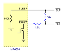
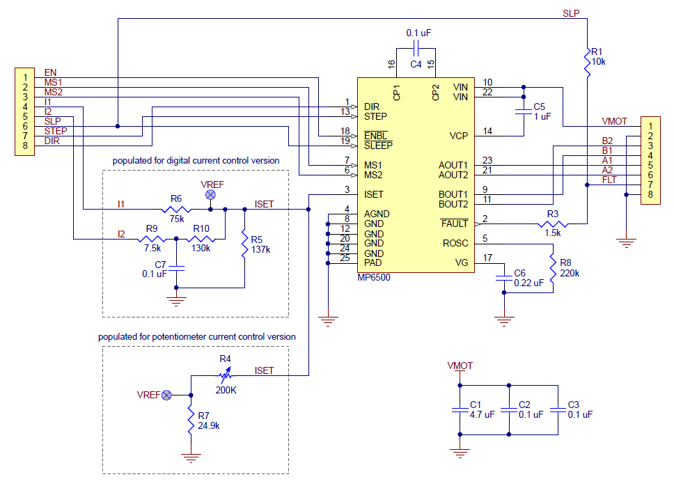
The MP6500 also features an open-drain FAULT output that drives low whenever the H-bridge FETs are disabled as the result of over-current protection, over-voltage protection, thermal shutdown, or under-voltage lockout protection. The carrier board connects this pin to the SLEEP pin through a 10 kΩ resistor that acts as a FAULT pull-up whenever SLEEP is externally held high, so no external pull-up is necessary on the FAULT pin. Note that the carrier includes a 1.5 kΩ protection resistor in series with the FAULT pin that makes it is safe to connect this pin directly to a logic voltage supply, as might happen if you use this board in a system designed for the pin-compatible A4988 carrier. In such a system, the 10 kΩ resistor between SLEEP and FAULT would then act as a pull-up for SLEEP, making the MP6500 carrier more of a direct replacement for the A4988 in such systems (the A4988 has an internal pull-up on its SLEEP pin).
| As a consequence of the connection between SLEEP and FAULT, active faults can pull the SLEEP pin low (below 2.1 V) if it is not externally pulled up strongly enough. We recommend any pull-up resistor used with SLEEP be 4.7 kΩ or stronger (or just connect SLEEP directly to VCC). |
Limitation du courant
Vidéo de Pololu (Youtube, anglais) concernant la limitation de courant.
{{#Widget:Iframe |url=https://www.youtube.com/embed/89BHS9hfSUk |width=420 |height=315 |border=0 }}
To achieve high step rates, the motor supply is typically higher than would be permissible without active current limiting. For instance, a typical stepper motor might have a maximum current rating of 1 A with a 5 Ω coil resistance, which would indicate a maximum motor supply of 5 V. Using such a motor with 9 V would allow higher step rates, but the current must actively be limited to under 1 A to prevent damage to the motor.
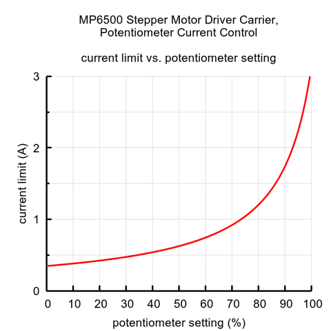
The MP6500 supports such active current limiting, and the trimmer potentiometer on the board can be used to set the current limit:
You will typically want to set the driver’s current limit to be at or below the current rating of your stepper motor. One way to set the current limit is to put the driver into full-step mode and to measure the current running through a single motor coil without clocking the STEP input. The measured current will be 0.7 times the current limit (since both coils are always on and limited to approximately 70% of the current limit setting in full-step mode).
Another way to set the current limit is to measure the VREF voltage and calculate the resulting current limit. The VREF voltage is accessible on a via that is circled on the bottom silkscreen of the circuit board. The current limit relates to VREF as follows:
So, the current limit in amps (A) is equal to 3.5 times the VREF voltage in volts (V), and if you have a stepper motor rated for 1 A, for example, you can set the current limit to about 1 A by setting the reference voltage to about 0.28 V. In practice, we have often observed the actual current limit to be about 10% (sometimes up to 15%) lower than what the equation and graph show.
The I1 and I2 pins are not used on this version of the MP6500 Stepper Motor Driver Carrier, and any signals applied to these pins will have no effect on the operation of the driver.
| The coil current can be very different from the power supply current, so you should not use the current measured at the power supply to set the current limit. The appropriate place to put your current meter is in series with one of your stepper motor coils. If the driver is in full-step mode, both coils will always be on and limited to approximately 70% of the current limit setting. If your driver is in one of the microstepping modes, the current through the coils will change with each step, ranging from 0% to 100% of the set limit. See the MP6500 datasheet for more information. |
Dissipation de puissance
The MP6500 driver IC has a maximum current rating of 2.5 A per coil, but the actual current you can deliver depends on how well you can keep the IC cool. The carrier’s printed circuit board is designed to draw heat out of the IC, but to supply more than approximately 1.5 A per coil, a heat sink or other cooling method is required. Note that the version of this board with digital current control has a maximum current limit setting of around 2 A.
| This product can get ***HOT*** enough to burn you long before the chip overheats. Take care when handling this product and other components connected to it. |
Please note that measuring the current draw at the power supply will generally not provide an accurate measure of the coil current. Since the input voltage to the driver can be significantly higher than the coil voltage, the measured current on the power supply can be quite a bit lower than the coil current (the driver and coil basically act like a switching step-down power supply). Also, if the supply voltage is very high compared to what the motor needs to achieve the set current, the duty cycle will be very low, which also leads to significant differences between average and RMS currents. Additionally, please note that the coil current is a function of the set current limit, but it does not necessarily equal the current limit setting as the actual current through each coil changes with each microstep.
Schéma
Où Acheter
Vous trouverez également les produits suivants:
A voir aussi
Documentation réalisée par Meurisse. D pour MCHobby.be. En partie basé sur les informations disponible sur le site de Pololu
Traduit avec l'autorisation de Pololu - Translated with the permission from Pololu - www.pololu.com
Toute référence, mention ou extrait de cette traduction doit être explicitement accompagné du texte suivant : « Traduction par MCHobby (www.MCHobby.be) - Vente de kit et composants » avec un lien vers la source (donc cette page) et ce quelque soit le média utilisé.
L'utilisation commercial de la traduction (texte) et/ou réalisation, même partielle, pourrait être soumis à redevance. Dans tous les cas de figures, vous devez également obtenir l'accord du(des) détenteur initial des droits. Celui de MC Hobby s'arrêtant au travail de traduction proprement dit.
