Pololu-Romi-Arm-Assembler
|
|
En cours de traduction/élaboration. |
Pince avec servo à retour de position
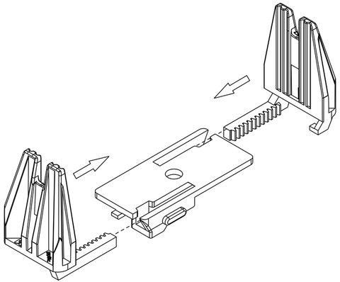
1. Faite glisser les deux palettes dans les glissières et pousser les jusqu'à ce qu'elles se rencontre au centre.
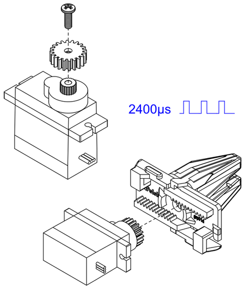
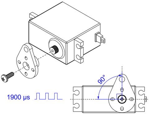
2. Installez et visser le pignon (engrenage) des palettes sur le micro servo et utilisez votre contrôleur servo pour placer le servo en position totalement fermé (impulsion de 2400 µs). Maintenez les palettes de la pince ensemble, placez le pignon entre les palettes. Assurez vous que le servo est orienté comme sur l'image.
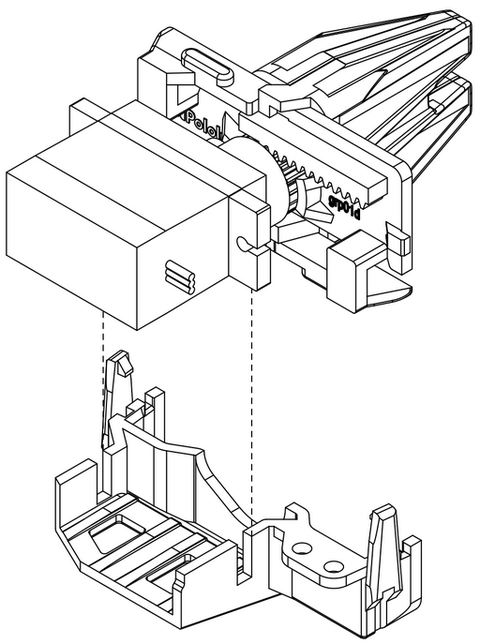
3. En maintenant les palette et le servo en place, glissez l'assemblage dans le boîtier inférieur de la pince.
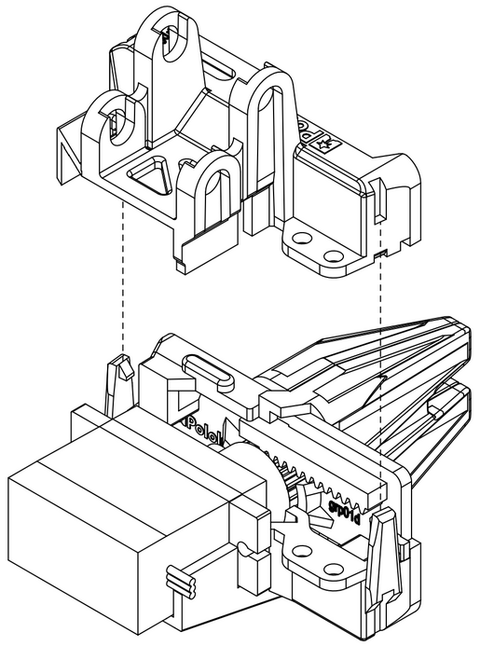
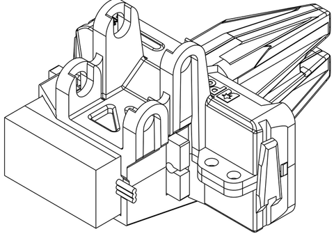
4. Alignez la partie supérieure du boîtier de la pince avec la partie inférieure et pressez les ensemble. Assurez vous que les clips soient bien fermés.
Votre pince est maintenant assemblée! Placez le de côté pour l'instant; il sera attaché à l'autre bout du bras une fois celui-ci assemblé.
| Si jamais vous aviez besoin d'ouvrir le boîtier de la pince alors pour pouvez relever les clips avec précaution pour écarter les deux éléments du boîtier. Un petit tournevis peut aider à passer sous les clips. |
Assemblage du bras Romi
| Ne serrez pas trop fort les vis. Les vis sont utilisées comme jointure du bras et devraient être fermement serrées mais pas trop pour ne pas déformer l'entretoise en nylon. Serrez trop fort les vis pourrait accroître la friction des jointures, ce qui accroîtra inutilement la charge sur les servos, pouvant potentiellement les endommager. |
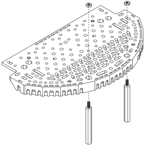
1. Puisque les servos seront xxxxxxxxxx will be mounted on top of the mounting holes for the standoffs, install the standoffs on the Romi expansion platform first. Start by putting the #2 nuts in the hexagonal holes shown below, and threading them onto the 38mm aluminum standoffs inserted through the mounting hole in the Romi expansion platform.
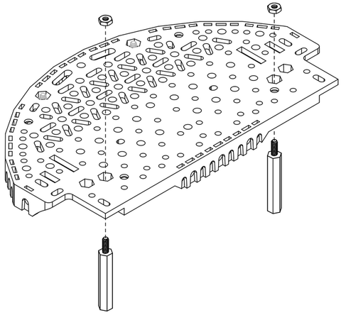
2. Do the same for the 25mm standoffs on the front of the platform. Note that you should be using the two mounting holes closer to the center of the chassis.
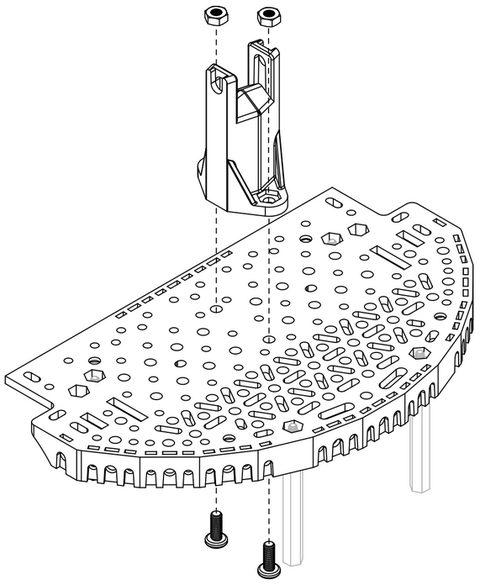
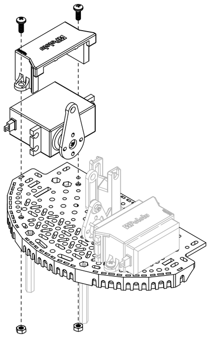
3. Next, install the pivot stand onto the Romi expansion platform using two 8 mm M3 screws and M3 nuts. The nuts should be seated into the cut-outs in the base of the stand.
4. Next, install the pivot stand onto the Romi expansion platform using two 8 mm M3 screws and M3 nuts. The nuts should be seated into the cut-outs in the base of the stand.
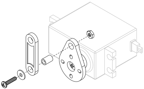
5. While the servo is easily accessible, now is a good time to install the short linkage on the lift servo horn. Start by aligning the linkage and inserting a 6 mm nylon spacer through the hole on both parts. Then, insert a 3/8″ #2-56 screw with a washer through the spacer and secure it with a #2 nut on the other side. All of the joints on the arm will use this same method (with appropriately sized screws and nylon spacers).
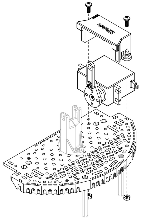
6. Use one of the servo mounting brackets to secure the lift servo to the right side of the Romi expansion platform using two 8 mm M3 screws and M3 nuts. The nuts should seat into the cutouts on the underside of the Romi expansion platform.
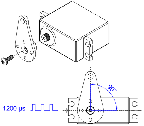
7. Prepare the tilt servo by using your servo controller to command it to move to its starting position (1200 µs pulse duration), then install the tilt servo horn with the included mounting screw, making sure it is aligned as shown.
8. Use the other servo mounting bracket to secure the tilt servo to the left side of the Romi expansion platform, again using two 8 mm M3 screws and M3 nuts.
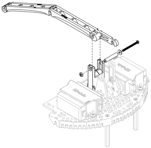
9. Use a 20 mm nylon spacer, 1″ #2-56 screw, a washer, and a #2 nut to install the main arm to the pivot stand as shown.
10. Use a 20 mm nylon spacer, 1″ #2-56 screw, a washer, and a #2 nut to install the main arm to the pivot stand as shown.
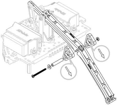
11. The next step is to install the two triangular pivot transfer linkages, one on either side of the main arm, making sure the direction indicator arrows are facing forward. Use a 20 mm nylon spacer, 1″ #2-56 screw, a washer, and a #2 nut to secure the 3 components together using the bottom-most hole in the triangular pivot transfer linkages.
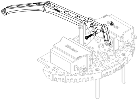
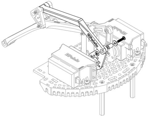
12. Connect the rear tilt arm to the top of the triangular pivot transfer linkages (again using a 20 mm nylon spacer, 1″ #2-56 screw, a washer, and a #2 nut). Then, secure the other side of the rear tilt arm to the tilt servo horn using a 6 mm nylon spacer, 3/8″ #2-56 screw, washer, and #2 nut.
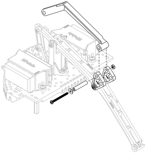
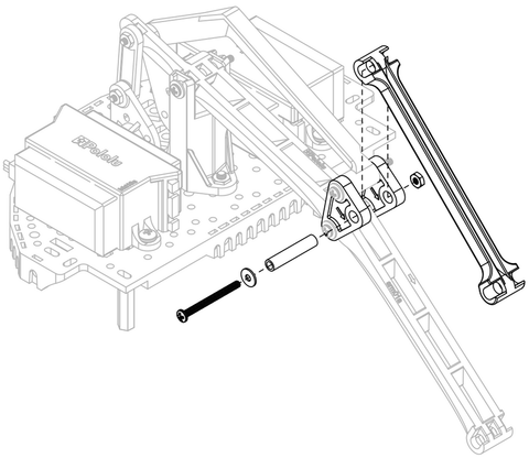
13. Using a 20 mm nylon spacer, 1″ #2-56 screw, a washer, and a #2 nut, connect the front tilt arm to the last available mounting holes on the triangular pivot transfer linkages, ensuring the direction indicator arrow on the underside of the front tilt arm is pointing forward.
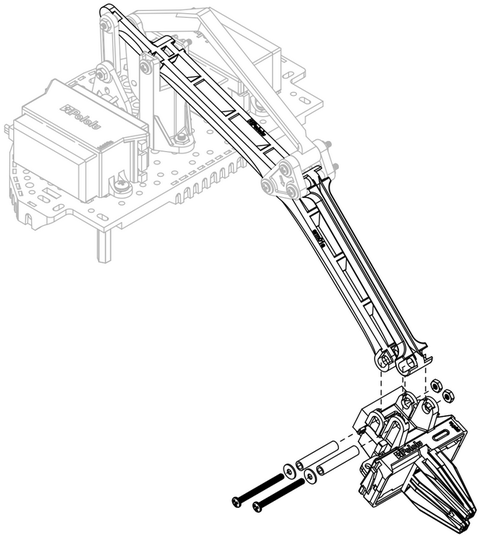
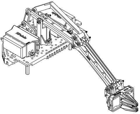
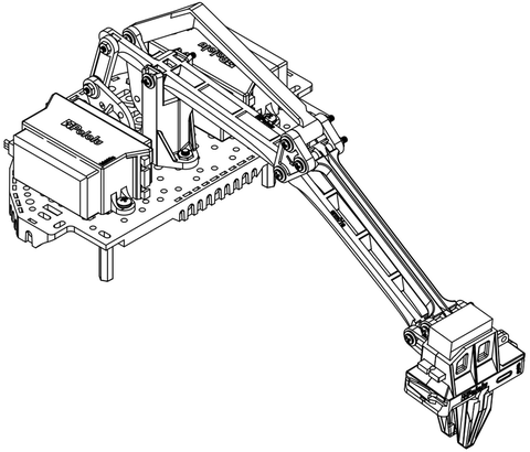
14. Attach the completed gripper sub-assembly to the end of the arm using a 20 mm nylon spacer, 1″ #2-56 screw, a washer, and a #2 nut for each joint. To keep the servo wires tidy, you can snake them back along the main arm through the holes down the spine.
The assembly of your Robot Arm Kit for the Romi is now complete!
The micro gripper can also be flipped around and used in an alternative orientation as shown below.
Installing on Romi
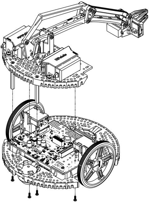
To install the arm accessory on the Romi chassis, align the rear aluminum standoffs with the mounting holes on the rear of the Romi Chassis. and the aluminum standoffs on the front of the arm assembly to the mounting holes nearest to the motors on the Romi chassis, as shown. Insert a 1/4″ #2-56 screw through each mounting hole from the bottom of the chassis, threading it into the standoff above.
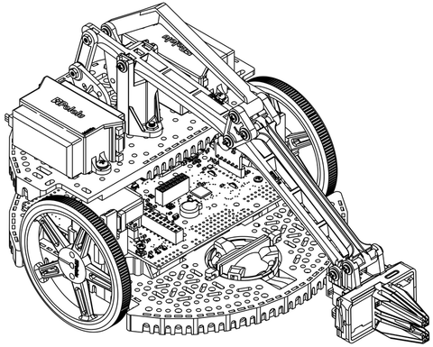
The Robot Arm accessory is now installed on the Romi chassis. You can tidy up the wiring for the gripper servo by running the wires along the main arm, passing the wire through the openings along the way, just be sure to leave the servo enough wire to accommodate the gripper’s full range of motion. Additionally, the two rear-most slots on the Romi expansion plate are large enough to pass the servo wires through so they can be routed down to the first level without leaving the profile of the chassis.
| Note: Lifting an object will generally cause the Romi to tilt forward, so we highly recommend using the optional second ball caster attachment. The front ball caster is supported by a flexible arm that acts as a suspension system. You can wrap a rubber band around the two hooks located on either side of the ball caster on the top side of the chassis to increase the stiffness of the suspension and help keep the robot stable. |
