Différences entre versions de « RASP-GPS-ULTIME-Brancher »
| Ligne 2 : | Ligne 2 : | ||
== Introduction == | == Introduction == | ||
| − | The easiest way to get start is to use an inexpensive [http://mchobby.be/PrestaShop/product.php?id_product=144 convertisseur USB vers TTL série] cable with your GPS module. | + | {{bloc-etroit|text=The easiest way to get start is to use an inexpensive [http://mchobby.be/PrestaShop/product.php?id_product=144 convertisseur USB vers TTL série] cable with your GPS module. |
You can of course use the HW UART directly on the Pi, but as you can see in this tutorial (Freeing UART on the Pi) it's a bit more complicated, and there are no secondary consequences with the USB adapter. | You can of course use the HW UART directly on the Pi, but as you can see in this tutorial (Freeing UART on the Pi) it's a bit more complicated, and there are no secondary consequences with the USB adapter. | ||
| − | This tutorial will assume that we are using the USB to TTL cable mentionned above, and that we are running on Occidentalis or Rasbian using the wonderfully painless WebIDE. Occidentalis & Rasbian already has the drivers for PL2303-based cables pre-installed, so you just need to plug it in and it should show up as /dev/ttyUSB0). | + | This tutorial will assume that we are using the USB to TTL cable mentionned above, and that we are running on Occidentalis or Rasbian using the wonderfully painless WebIDE. Occidentalis & Rasbian already has the drivers for PL2303-based cables pre-installed, so you just need to plug it in and it should show up as /dev/ttyUSB0).}} |
== Brancher le Breakout == | == Brancher le Breakout == | ||
| Ligne 12 : | Ligne 12 : | ||
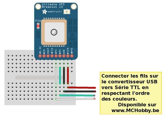
The first thing you'll need to do is to hook your Ultimate GPS Breakout up to the Pi with the adapter cable. The following diagram shows you what you need to know, essentially just connecting the cables of the same color together. | The first thing you'll need to do is to hook your Ultimate GPS Breakout up to the Pi with the adapter cable. The following diagram shows you what you need to know, essentially just connecting the cables of the same color together. | ||
| − | [[Fichier:RASP-GPS-ULTIME-Brancher-01.jpg]] | + | [[Fichier:RASP-GPS-ULTIME-Brancher-01.jpg|640px]] |
While the module on the Ultimate GPS Breakout has an exceptionally sensitive antenna and may work indoors as is, you may want to pick up an [http://mchobby.be/PrestaShop/product.php?id_product=244 external GPS Antenna] et un câble [http://mchobby.be/PrestaShop/product.php?id_product=243 adaptateur SMA vers uFL/u.FL/IPX/IPEX RF] if this is for indoor use. This will allow you to keep the Pi and GPS breakout indoors, but run the antenna out a window or at least near one for improved reliability ans signal integrity. | While the module on the Ultimate GPS Breakout has an exceptionally sensitive antenna and may work indoors as is, you may want to pick up an [http://mchobby.be/PrestaShop/product.php?id_product=244 external GPS Antenna] et un câble [http://mchobby.be/PrestaShop/product.php?id_product=243 adaptateur SMA vers uFL/u.FL/IPX/IPEX RF] if this is for indoor use. This will allow you to keep the Pi and GPS breakout indoors, but run the antenna out a window or at least near one for improved reliability ans signal integrity. | ||
Version du 24 juillet 2013 à 18:25
Introduction
The easiest way to get start is to use an inexpensive convertisseur USB vers TTL série cable with your GPS module.
You can of course use the HW UART directly on the Pi, but as you can see in this tutorial (Freeing UART on the Pi) it's a bit more complicated, and there are no secondary consequences with the USB adapter.
This tutorial will assume that we are using the USB to TTL cable mentionned above, and that we are running on Occidentalis or Rasbian using the wonderfully painless WebIDE. Occidentalis & Rasbian already has the drivers for PL2303-based cables pre-installed, so you just need to plug it in and it should show up as /dev/ttyUSB0).
Brancher le Breakout
The first thing you'll need to do is to hook your Ultimate GPS Breakout up to the Pi with the adapter cable. The following diagram shows you what you need to know, essentially just connecting the cables of the same color together.
While the module on the Ultimate GPS Breakout has an exceptionally sensitive antenna and may work indoors as is, you may want to pick up an external GPS Antenna et un câble adaptateur SMA vers uFL/u.FL/IPX/IPEX RF if this is for indoor use. This will allow you to keep the Pi and GPS breakout indoors, but run the antenna out a window or at least near one for improved reliability ans signal integrity.
Configurer l'adaptateur USB
Once you plug the USB cable into the Pi, the adapter should show up as /dev/ttyUSB0 (though the '0' may be different if you have other ttyUSB adapters present).
You can see a list of all ttyUSB devices by entering the following into the console (I'm using the 'terminal' feature in Adafruit's browser-based WebIDE here for convenience sake!):
ls /dev/ttyUSB*
If you have any problems, you can enter the following command to see the USB devices on your Pi:
sudo lsusb
Which should show you the USB adapter (Prolific PL2303), as follows:
If you just want to do a quick check to see what data is coming out of the GPS, you can enter the following command, following by CTRL+ to quit:
sudo cat /dev/ttyUSB0
Installing a GPS Daemon (gpsd)
The next step is installing some software on your Raspberry Pi that understands the serial data that your GPS module is providing via /dev/ttyUSB0. Thankfully other people have already done all the hard work for you of properly parsing the raw GPS data, and we can use (amongst other options) a nice little package named 'gpsd', which essentially acts as a layer between your applications and the actual GPS hardware, gracefully handling parsing errors, and providing a common, well-defined interfaces to any GPS module.
To install gpsd, simply run the following commands from the console:
sudo apt-get install gpsd gpsd-clients python-gps
... which will install the required packages (an internet connection will be required for this step!)
sudo gpsd /dev/ttyUSB0 -F /var/run/gpsd.sock
... which will point the gps daemon to our GPS device on the USB to TTY adapter cable (simply substitute '/dev/ttyUSB0' for another destination if required).
Testing it Out
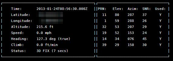
After a few seconds, gpsd should open up the proper socket and if the GPS is locked we should be able to get some data from the GPS module.
To test this, we can use the following command:
cgps -s
If you have a fix, you'll see something like the following information in the terminal window:
| If you have any problems and cgps always displays 'NO FIX' under status and then aborts after a few seconds, you may need to restart the gpsd service. You can do that via the following commands: |
sudo killall gpsd
sudo gpsd /dev/ttyUSB0 -F /var/run/gpsd.sock
Source: Adafruit Ultimate GPS on the Raspberry Pi écrit par Kevin Townsend pour Adafruit Industrie
Traduction réalisée par Meurisse D pour MCHobby.be.
Créé par Kevin Townsend pour AdaFruit Industries.
Toute référence, mention ou extrait de cette traduction doit être explicitement accompagné du texte suivant : « Traduction par MCHobby (www.MCHobby.be) - Vente de kit et composants » avec un lien vers la source (donc cette page) et ce quelque soit le média utilisé.
L'utilisation commercial de la traduction (texte) et/ou réalisation, même partielle, pourrait être soumis à redevance. Dans tous les cas de figures, vous devez également obtenir l'accord du(des) détenteur initial des droits. Celui de MC Hobby s'arrêtant au travail de traduction proprement dit.
Traduit avec l'autorisation d'AdaFruit Industries - Translated with the permission from Adafruit Industries - www.adafruit.com


