Différences entre versions de « Rasp-Hack-Afficheur-LCD-Breadboard »
(Page créée avec « {{Rasp-Hack-Afficheur-LCD-NAV}} xx {{Rasp-Hack-Afficheur-LCD-TRAILER}} ») |
|||
| Ligne 1 : | Ligne 1 : | ||
{{Rasp-Hack-Afficheur-LCD-NAV}} | {{Rasp-Hack-Afficheur-LCD-NAV}} | ||
| − | + | [[Fichier:Rasp-Hack-Afficheur-LCD-Montage-01.jpg]] | |
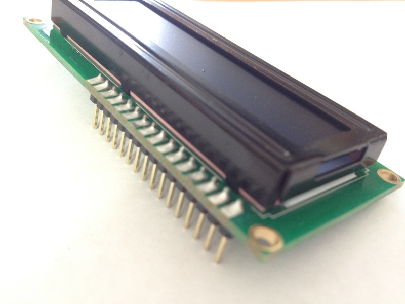
| + | Whenever you come across a LCD that looks like it has 16 connectors it is most likely using a HD44780 controller. These devices provide the same pinouts making them relatively easy to work with. The LCD uses a parallel interface meaning that we will need many pins from our raspberry pi to control it. In this tutorial we will use 4 data pins (4-bit mode) and two control pins. | ||
| + | |||
| + | The '''data pins''' are straight forward. They are sending data to the display (toggled high/low). We will only be using write mode and not reading any data. | ||
| + | |||
| + | The '''register select''' pin has two uses. When pulled low it can send commands to the LCD (like position to move to, or clear the screen). This is referred to as writing to the instruction or command register. When toggled the other way (1) the register select pin goes into a data mode and will be used to send data to the screen. | ||
| + | |||
| + | The '''read/write''' pin will be pulled low (write only) as we only want to write to the LCD based on this setup. | ||
| + | |||
| + | The '''enable''' pin will be toggled to write data to the registers. | ||
| + | |||
| + | == Brochage du LCD == | ||
| + | # Ground | ||
| + | # VCC - 5v not 3.3v | ||
| + | # Contrast adjustment (VO) from potentiometer | ||
| + | # Register Select (RS). RS=0: Command, RS=1: Data | ||
| + | # Read/Write (R/W). R/W=0: Write, R/W=1: Read (we won't use this pin) | ||
| + | # Clock (Enable). Falling edge triggered | ||
| + | # Bit 0 (Not used in 4-bit operation) | ||
| + | # Bit 1 (Not used in 4-bit operation) | ||
| + | # Bit 2 (Not used in 4-bit operation) | ||
| + | # Bit 3 (Not used in 4-bit operation) | ||
| + | # Bit 4 | ||
| + | # Bit 5 | ||
| + | # Bit 6 | ||
| + | # Bit 7 | ||
| + | # Backlight LED Anode (+) | ||
| + | # Backlight LED Cathode (-) | ||
| + | |||
| + | == Diagramme de câblage == | ||
| + | |||
| + | [[Fichier:Rasp-Hack-Afficheur-LCD-Montage-02.jpg]] | ||
| + | |||
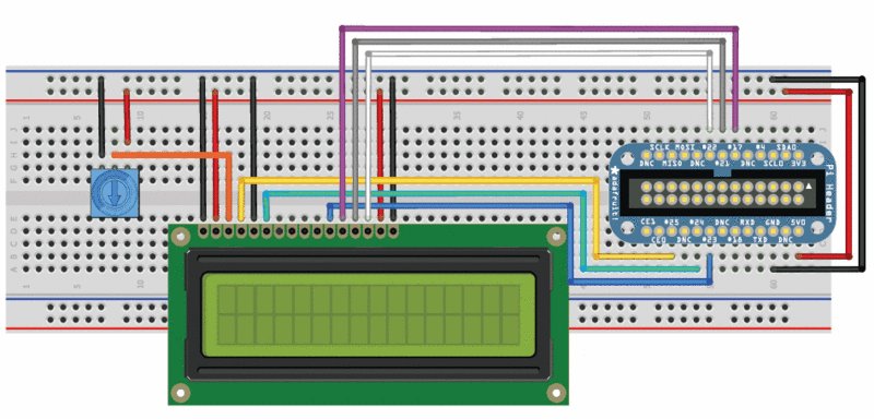
| + | First, connect the cobber power pins to the breadboard power rail. +5.0V from the cobbler goes to the red striped rail (red wire) and GND from the cobbler goes to the blue striped rail (black wire) | ||
| + | |||
| + | In order to send data to the LCD we are going to wire it up as follows | ||
| + | |||
| + | * Pin #1 of the LCD goes to ground (black wire) | ||
| + | * Pin #2 of the LCD goes to +5V (red wire) | ||
| + | * Pin #3 (Vo) connects to the middle of the potentiometer (orange wire) | ||
| + | * Pin #4 (RS) connects to the Cobber #25 (yellow wire) | ||
| + | * Pin #5 (RW) goes to ground (black wire) | ||
| + | * Pin #6 (EN) connects to cobber #24 (green wire) | ||
| + | * Skip LCD Pins #7, #8, #9 and #10 | ||
| + | * Pin #11 (D4) connects to cobber #23 (blue wire) | ||
| + | * Pin #12 (D5) connects to cobber #17 (violet wire) | ||
| + | * Pin #13 (D6) connects to cobber #21 (gray wire) | ||
| + | * Pin #14 (D7) connects to cobber #22 (white wire) | ||
| + | * Pin #15 (LED +) goes to +5V (red wire) | ||
| + | * Pin #16 (LED -) goes to ground (black wire) | ||
| + | |||
| + | Then connect up the potentiometer, the left pin connects to ground (black wire) and the right pin connects to +5V (red wire) | ||
| + | |||
| + | == Schéma == | ||
| + | |||
| + | [[Fichier:Rasp-Hack-Afficheur-LCD-Montage-03.png]] | ||
| + | |||
| + | == Afficheur LCD 5V et Pi 3.3v == | ||
| + | |||
| + | The raspberry Pi GPIOs are designed for 3.3v, but our LCD is a 5v device. It's fine to use a 5v display, but only if we are sending data out of the Pi. We are not going to use the 3.3v power rail on the cobbler and we will tie the RW (read/write) pin of the display to GND as we do not want the display sending sending a 5v signal into the Pi. | ||
| + | |||
| + | <font color="red"><strong>N'inverser les connexion!</strong></font> | ||
| + | |||
| + | == Préparer le LCD == | ||
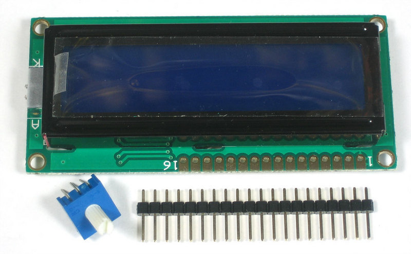
| + | Before you start, make sure you have a strip of 0.1" male header and a 10K potentiometer. All Adafruit Character LCDs come with these parts so you should be good to go. | ||
| + | |||
| + | [[Fichier:Rasp-Hack-Afficheur-LCD-Montage-LCD-01.jpg]] | ||
| + | |||
| + | Most LCDs have a strip of 16 pins on the top, if the header is a little longer, just break it off until its the right length | ||
| + | |||
| + | [[Fichier:Rasp-Hack-Afficheur-LCD-Montage-LCD-02.jpg]] | ||
| + | |||
| + | Next you'll need to solder the header to the LCD.You must do this, '''it is not OK to just try to 'press fit' the LCD'''! | ||
| + | |||
| + | [[Fichier:Rasp-Hack-Afficheur-LCD-Montage-LCD-03.jpg]] | ||
| + | |||
| + | Start by connecting the '''5V''' and '''GND''' wires from the cobbler to the breadboard. Then connect pins #1, #2 and #15, #16 to the breadboard power rails as shown. The backlight should come on. If it doesn't, check the wiring! | ||
| + | |||
| + | [[Fichier:Rasp-Hack-Afficheur-LCD-Montage-LCD-04.jpg]] | ||
| + | |||
| + | [[Fichier:Rasp-Hack-Afficheur-LCD-Montage-LCD-05.jpg]] | ||
| + | |||
| + | Next, wire up the contrast potentiometer as shown above, with the middle pin connecting to LCD pin #3 and the other two pins going to 5V and ground. | ||
| + | |||
| + | Twist the potentiometer until you see the first line of the LCD fill with boxes. If you don't see the boxes, check your wiring! | ||
| + | |||
| + | [[Fichier:Rasp-Hack-Afficheur-LCD-Montage-LCD-06.jpg]] | ||
| + | |||
| + | Finish the wiring for the '''RS, RW, EN, D4, D5, D6''', and '''D7''' pins as shown in the diagram up top | ||
| + | |||
| + | [[Fichier:Rasp-Hack-Afficheur-LCD-Montage-LCD-07.jpg]] | ||
| + | |||
| + | That's it! Now you're ready to run the python script to draw text on the screen! | ||
| + | |||
{{Rasp-Hack-Afficheur-LCD-TRAILER}} | {{Rasp-Hack-Afficheur-LCD-TRAILER}} | ||
Version du 27 janvier 2013 à 16:42
Whenever you come across a LCD that looks like it has 16 connectors it is most likely using a HD44780 controller. These devices provide the same pinouts making them relatively easy to work with. The LCD uses a parallel interface meaning that we will need many pins from our raspberry pi to control it. In this tutorial we will use 4 data pins (4-bit mode) and two control pins.
The data pins are straight forward. They are sending data to the display (toggled high/low). We will only be using write mode and not reading any data.
The register select pin has two uses. When pulled low it can send commands to the LCD (like position to move to, or clear the screen). This is referred to as writing to the instruction or command register. When toggled the other way (1) the register select pin goes into a data mode and will be used to send data to the screen.
The read/write pin will be pulled low (write only) as we only want to write to the LCD based on this setup.
The enable pin will be toggled to write data to the registers.
Brochage du LCD
- Ground
- VCC - 5v not 3.3v
- Contrast adjustment (VO) from potentiometer
- Register Select (RS). RS=0: Command, RS=1: Data
- Read/Write (R/W). R/W=0: Write, R/W=1: Read (we won't use this pin)
- Clock (Enable). Falling edge triggered
- Bit 0 (Not used in 4-bit operation)
- Bit 1 (Not used in 4-bit operation)
- Bit 2 (Not used in 4-bit operation)
- Bit 3 (Not used in 4-bit operation)
- Bit 4
- Bit 5
- Bit 6
- Bit 7
- Backlight LED Anode (+)
- Backlight LED Cathode (-)
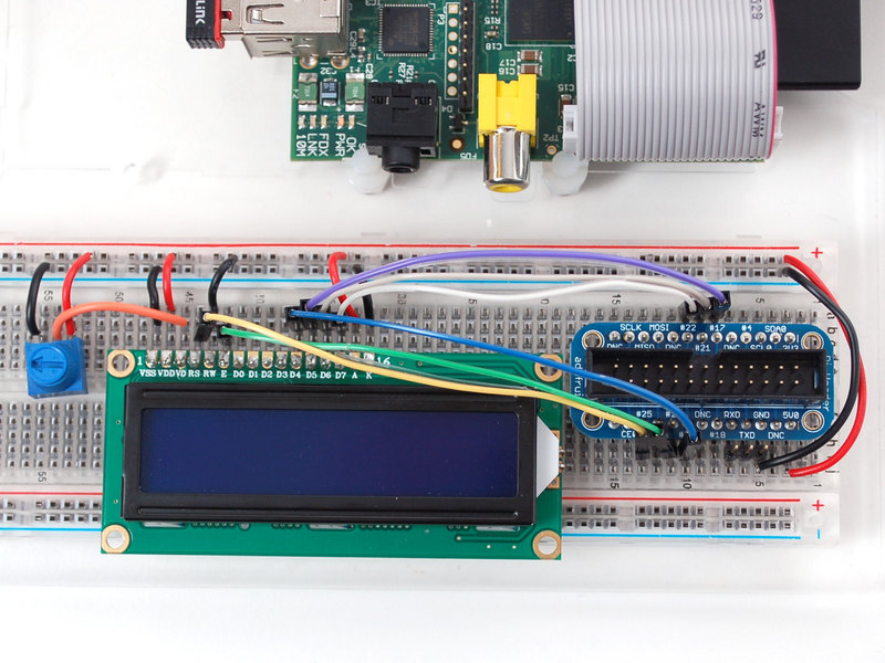
Diagramme de câblage
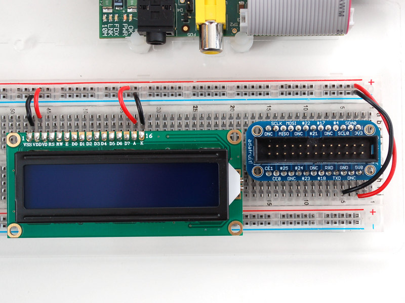
First, connect the cobber power pins to the breadboard power rail. +5.0V from the cobbler goes to the red striped rail (red wire) and GND from the cobbler goes to the blue striped rail (black wire)
In order to send data to the LCD we are going to wire it up as follows
- Pin #1 of the LCD goes to ground (black wire)
- Pin #2 of the LCD goes to +5V (red wire)
- Pin #3 (Vo) connects to the middle of the potentiometer (orange wire)
- Pin #4 (RS) connects to the Cobber #25 (yellow wire)
- Pin #5 (RW) goes to ground (black wire)
- Pin #6 (EN) connects to cobber #24 (green wire)
- Skip LCD Pins #7, #8, #9 and #10
- Pin #11 (D4) connects to cobber #23 (blue wire)
- Pin #12 (D5) connects to cobber #17 (violet wire)
- Pin #13 (D6) connects to cobber #21 (gray wire)
- Pin #14 (D7) connects to cobber #22 (white wire)
- Pin #15 (LED +) goes to +5V (red wire)
- Pin #16 (LED -) goes to ground (black wire)
Then connect up the potentiometer, the left pin connects to ground (black wire) and the right pin connects to +5V (red wire)
Schéma
Afficheur LCD 5V et Pi 3.3v
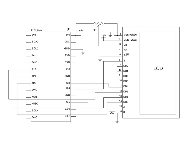
The raspberry Pi GPIOs are designed for 3.3v, but our LCD is a 5v device. It's fine to use a 5v display, but only if we are sending data out of the Pi. We are not going to use the 3.3v power rail on the cobbler and we will tie the RW (read/write) pin of the display to GND as we do not want the display sending sending a 5v signal into the Pi.
N'inverser les connexion!
Préparer le LCD
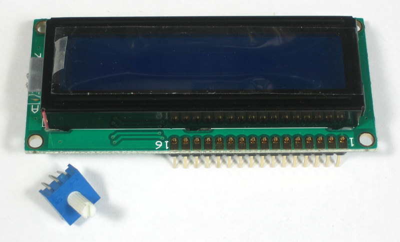
Before you start, make sure you have a strip of 0.1" male header and a 10K potentiometer. All Adafruit Character LCDs come with these parts so you should be good to go.
Most LCDs have a strip of 16 pins on the top, if the header is a little longer, just break it off until its the right length
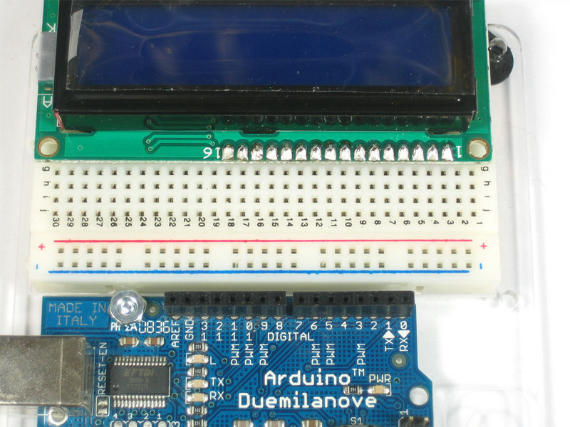
Next you'll need to solder the header to the LCD.You must do this, it is not OK to just try to 'press fit' the LCD!
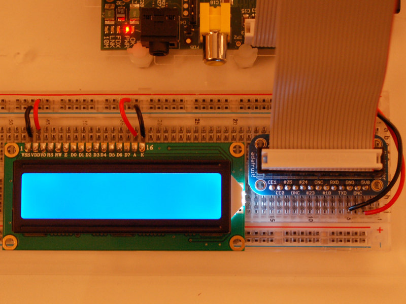
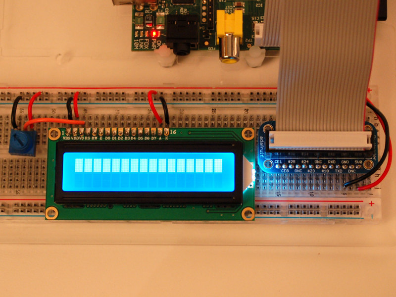
Start by connecting the 5V and GND wires from the cobbler to the breadboard. Then connect pins #1, #2 and #15, #16 to the breadboard power rails as shown. The backlight should come on. If it doesn't, check the wiring!
Next, wire up the contrast potentiometer as shown above, with the middle pin connecting to LCD pin #3 and the other two pins going to 5V and ground.
Twist the potentiometer until you see the first line of the LCD fill with boxes. If you don't see the boxes, check your wiring!
Finish the wiring for the RS, RW, EN, D4, D5, D6, and D7 pins as shown in the diagram up top
That's it! Now you're ready to run the python script to draw text on the screen!
Source: Character LCD with Raspberry Pi or BeagleBone Black écrit par Tony Dicola pour Adafruit Industries.
Traduit avec l'autorisation d'AdaFruit Industries - Translated with the permission from Adafruit Industries - www.adafruit.com
Toute référence, mention ou extrait de cette traduction doit être explicitement accompagné du texte suivant : « Traduction par MCHobby (www.MCHobby.be) - Vente de kit et composants » avec un lien vers la source (donc cette page) et ce quelque soit le média utilisé.
L'utilisation commercial de la traduction (texte) et/ou réalisation, même partielle, pourrait être soumis à redevance. Dans tous les cas de figures, vous devez également obtenir l'accord du(des) détenteur initial des droits. Celui de MC Hobby s'arrêtant au travail de traduction proprement dit.
