Senseur IR Intervalometre
Maintenant qu'il est possible de lire des codes IR, il est temps de
passer à notre premier projet.
Ce projet projet sera un intervallomètre.
Un intervallomètre est une fonction de certains appareils
photographiques qui permet de faire des images à des intervalles
de temps définis.
Les intervallomètres sont utilisés pour voir en accéléré des
phénomènes lents comme la croissance de plantes, le déplacement
de nuages (voir cet article WikiPedia pour plus d'information)
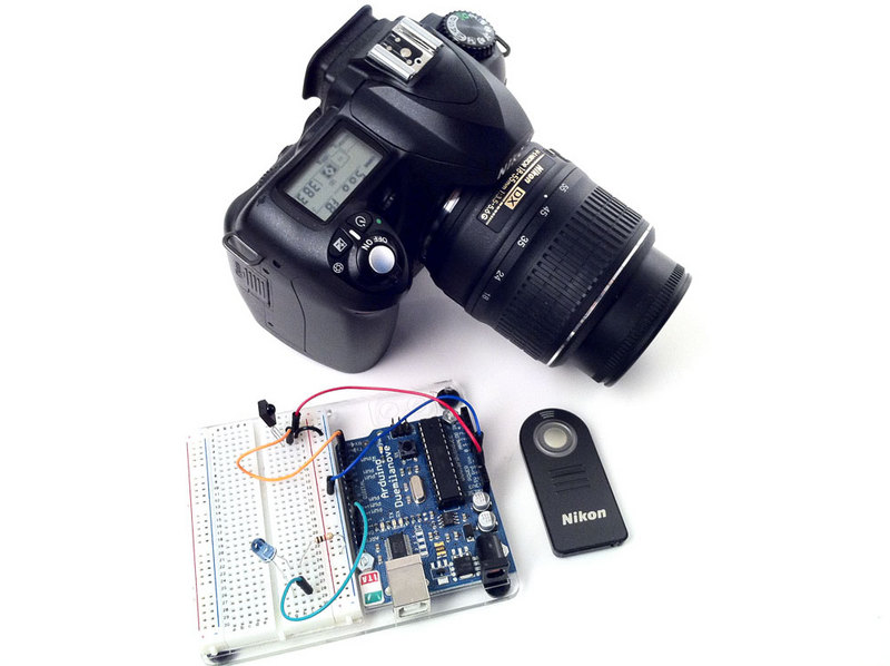
Si votre appareil ne dispose pas d'une fonction intervallomètre, il est possible d'utiliser une diode infrarouge (et un senseur IR) pour envoyer un signal de prise de photographie à intervalle régulier (quelques minutes par exemple).
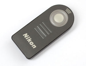
La caméra utilisé dans ce projet dispose d'une télécommande infra-rouge que vous pouvez utiliser avec l'appareil photo (la plupart des appareils haute gamme en dispose).
Premièrement, nous allons décoder (lire) le signal infrarouge émis par la télécommande lorsque le bouton est pressé. Ensuite, nous allons réutiliser ces données pour commander la broche de la LED Infrarouge raccordée sur notre Arduino. Ce code sera envoyé une fois par minute.
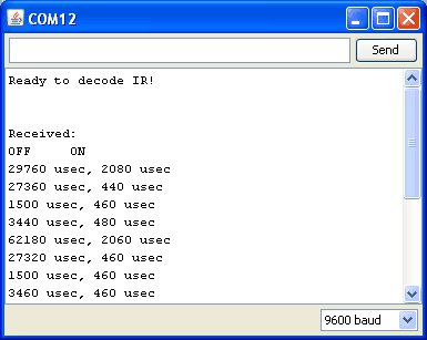
Cette première étape est simple. Pointez la télécommande vers le senseur infrarouge et pressez le bouton. En utilisant la télécommande Nikon ML-L3 nous avons obtenu le signal suivant:
Looks like the data sent is:
suite ici [1]
| PWM ON | OFF |
| 2.0 ms | 2.7 ms |
| 0.4 ms | 1.5 ms |
| 0.5 ms | 3.5 ms |
| 0.5 ms | 62.2 ms |
| 2.0 ms | 2.7 ms |
| 0.5 ms | 1.5 ms |
| 0.5 ms | 3.5 ms |
| 0.5 ms |
If you look closely you'll see its actually just
| PWM ON | OFF |
| 2.0 ms | 2.7 ms |
| 0.4 ms | 1.5 ms |
| 0.5 ms | 3.5 ms |
| 0.5 ms | 62.2 ms |
sent twice. Sending the same signal twice is very common - doubling up to make sure it gets received
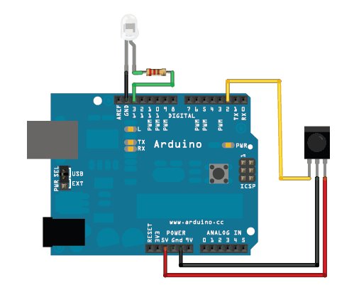
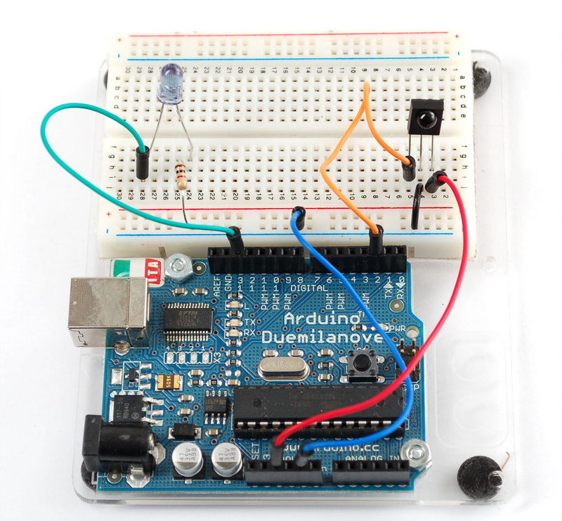
Next up we'll need to connect an IR 940nm LED to the output of the Arduino
Then we'll write a sketch which will pulse pin #13 on and off very fast in the proper code sequence.
    // This sketch will send out a Nikon D50 trigger signal (probably works with most Nikons)
    // See the full tutorial at http://www.ladyada.net/learn/sensors/ir.html
    // this code is public domain, please enjoy!
    int IRledPin = 13; // LED connected to digital pin 13
    // The setup() method runs once, when the sketch starts
    void setup() {
    // initialize the IR digital pin as an output:
    pinMode(IRledPin, OUTPUT);
    Serial.begin(9600);
    }
    void loop()
    {
    Serial.println("Sending IR signal");
    SendNikonCode();
    delay(60*1000); // wait one minute (60 seconds * 1000 milliseconds)
    }
    // This procedure sends a 38KHz pulse to the IRledPin
    // for a certain # of microseconds. We'll use this whenever we need to send codes
    void pulseIR(long microsecs) {
    // we'll count down from the number of microseconds we are told to wait
    cli(); // this turns off any background interrupts
    while (microsecs > 0) {
    // 38 kHz is about 13 microseconds high and 13 microseconds low
    digitalWrite(IRledPin, HIGH); // this takes about 3 microseconds to happen
    delayMicroseconds(10); // hang out for 10 microseconds, you can also change this to 9 if its not working
    digitalWrite(IRledPin, LOW); // this also takes about 3 microseconds
    delayMicroseconds(10); // hang out for 10 microseconds, you can also change this to 9 if its not working
    // so 26 microseconds altogether
    microsecs -= 26;
    }
    sei(); // this turns them back on
    }
    void SendNikonCode() {
    // This is the code for my particular Nikon, for others use the tutorial
    // to 'grab' the proper code from the remote
    pulseIR(2080);
    delay(27);
    pulseIR(440);
    delayMicroseconds(1500);
    pulseIR(460);
    delayMicroseconds(3440);
    pulseIR(480);
    delay(65); // wait 65 milliseconds before sending it again
    pulseIR(2000);
    delay(27);
    pulseIR(440);
    delayMicroseconds(1500);
    pulseIR(460);
    delayMicroseconds(3440);
    pulseIR(480);
    }
void pulseIR(long microsecs) is our helper procedure, it will create the PWM IR signal like we saw before. I used my scope to fine-tune it so that the delays added up right. We use the not-often-discussedcli()and sei()procedures to turn off interrupts. The arduino does a couple things in the background like looking for serial data to read or write, keeping track of time, etc. Most of the time we can just ignore it but for delicate high speed signals like this we want to keep quiet so that we get a nice clean signal
If you look at SendNikonCode() you will see the IR command code that we deduced in the previous project by timing the pulses from the IR sensor.
We wired this up and it worked great, make sure to point the IR LED at the camera properly
You can also get the latest code at github
Traduit avec l'autorisation d'AdaFruit Industries - Translated with the permission from Adafruit Industries - www.adafruit.com
Toute référence, mention ou extrait de cette traduction doit être explicitement accompagné du texte suivant : « Traduction par MCHobby (www.MCHobby.be) - Vente de kit et composants » avec un lien vers la source (donc cette page) et ce quelque soit le média utilisé.
L'utilisation commercial de la traduction (texte) et/ou réalisation, même partielle, pourrait être soumis à redevance. Dans tous les cas de figures, vous devez également obtenir l'accord du(des) détenteur initial des droits. Celui de MC Hobby s'arrêtant au travail de traduction proprement dit.
