Différences entre versions de « Senseur Température »
| Ligne 83 : | Ligne 83 : | ||
Unlike the FSR or photocell sensors we have looked at, the TMP36 and friends doesn't act like a resistor. Because of that, there is really only one way to read the temperature value from the sensor, and that is plugging the output pin directly into an Analog (ADC) input. | Unlike the FSR or photocell sensors we have looked at, the TMP36 and friends doesn't act like a resistor. Because of that, there is really only one way to read the temperature value from the sensor, and that is plugging the output pin directly into an Analog (ADC) input. | ||
| − | [[Fichier:TMP36-breadboard.jpg| | + | [[Fichier:TMP36-breadboard.jpg|550px]] |
Remember that you can use anywhere between 2.7V and 5.5V as the power supply. For this example I'm showing it with a 5V supply but note that you can use this with a 3.3v supply just as easily. No matter what supply you use, the analog voltage reading will range from about 0V (ground) to about 1.75V. | Remember that you can use anywhere between 2.7V and 5.5V as the power supply. For this example I'm showing it with a 5V supply but note that you can use this with a 3.3v supply just as easily. No matter what supply you use, the analog voltage reading will range from about 0V (ground) to about 1.75V. | ||
Version du 6 janvier 2013 à 12:48
|
|
En cours de traduction |
Présentation
Introduction
An analog temperature sensor is pretty easy to explain, its a chip that tells you what the ambient temperature is!
These sensors use a solid-state technique to determine the temperature. That is to say, they don't use mercury (like old thermometers), bimetalic strips (like in some home thermometers or stoves), nor do they use thermistors (temperature sensitive resistors). Instead, they use the fact as temperature increases, the voltage across a diode increases at a known rate. (Technically, this is actually the voltage drop between the base and emitter - the Vbe - of a transistor.) By precisely amplifying the voltage change, it is easy to generate an analog signal that is directly proportional to temperature. There have been some improvements on the technique but, essentially that is how temperature is measured.
Because these sensors have no moving parts, they are precise, never wear out, don't need calibration, work under many environmental conditions, and are consistant between sensors and readings. Moreover they are very inexpensive and quite easy to use.
Quelques informations
These stats are for the temperature sensor in the Adafruit shop, the Analog Devices TMP36 (-40 to 150C). Its very similar to the LM35/TMP35 (celsius output) and LM34/TMP34 (farenheit output). The reason we went with the '36 instead of the '35 or '34 is that this sensor has a very wide range and doensn't require a negative voltage to read sub-zero temperatures. Otherwise, the functionality is basically the same.
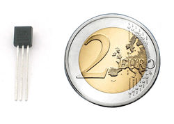
- Taille: boitier TO-92 à 3 broches (similaire à un transistor)
- Prix: ~2.50 eur disponible chez MCHobby
- Gamme de température: -40°C a 150°C / -40°F a 302°F
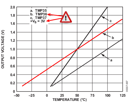
- Tension de sortie: 0.1V (-40°C) to 2.0V (150°C) mais la précision diminue après 125°C
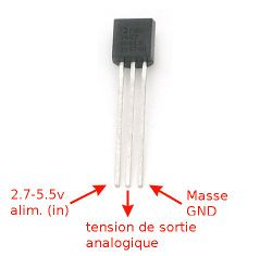
- Tension d'alimentation: 2.7V a 5.5V
- Courant de charge: 0.05 mA
- Fiche technique
Comment mesurer la température
Comment calculer la température Il faut donc convertir la tension analogique en degré. Comme le TMP36 permet de mesurer des température négatives, le 0 degré Celsius est placé à une offset de 500 milliVolts. Ainsi, toute mesure inférieur à 500 mv correspondra à une température négative.
La formule est la suivante pour le TMP36:
Temp en °C = ( Tension_de_sortie_en_milliVolts - 500) / 10
Donc, si la tension de sortie est de 1 Volts, la température correspondante est de
(1000 - 500)/10
Soit 50 degrés Celcius.
si vous utilisez un LM35 ou similaire, la température se calcule comme suit (utiliser la ligne 'a' sur le graphique):
Temp en °C = ( Tension_de_sortie_en_millivolts) / 10
Utilisation de plusieurs senseurs
Vous pourriez rencontrer des problèmes si vous utilisez de multiples senseurs analogiques. Problems you may encounter with multiple sensors: If, when adding more sensors, you find that the temperature is inconsistant, this indicates that the sensors are interfering with each other when switching the analog reading circuit from one pin to the other. You can fix this by doing two delayed readings and tossing out the first one
Vous obtiendrez plus d'information en lisant cet article (en anglais)
Tester le senseur
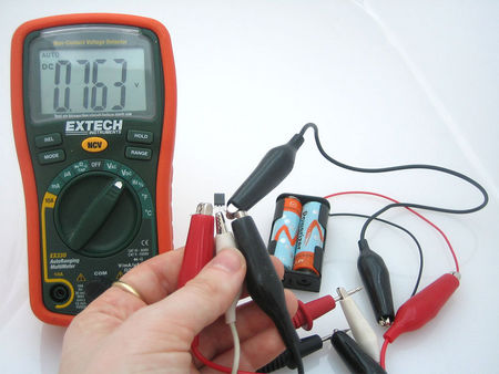
Testing these sensors is pretty easy but you'll need a battery pack or power supply.
Connect a 2.7-5.5V power supply (2-4 AA batteries work fantastic) so that ground is connected to pin 3 (right pin), and power is connected to pin 1 (left pin)
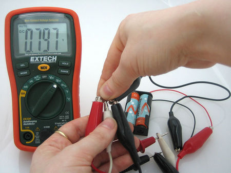
Then connect your multimeter in DC voltage mode to ground and the remaining pin 2 (middle). If you've got a TMP36 and its about room temperature (25°C), the voltage should be about 0.75V. Note that if you're using a LM35, the voltage will be 0.25V
The sensor is indicating that the temperature is 26.3°C also known as 79.3°F
You can change the voltage range by pressing the plastic case of the sensor with your fingers, you will see the temperature/voltage rise.
With my fingers on the sensor, heating it up a little, the temperature reading is now 29.7°C / 85.5°F
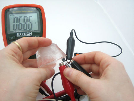
Or you can touch the sensor with an ice cube, perferrably in a plastic bag so it doesn't get water on your circuit, and see the temperature/voltage drop.
I pressed an ice-cube against the sensor, to bring the temperature down to 18.6°C / 65.5°F
Utiliser le senseur
Connecter un senseur de température
Connecting to a Temperature Sensor These sensors have little chips in them and while they're not that delicate, they do need to be handled properly. Be careful of static electricity when handling them and make sure the power supply is connected up correctly and is between 2.7 and 5.5V DC - so don't try to use a 9V battery!
They come in a "TO-92" package which means the chip is housed in a plastic hemi-cylinder with three legs. The legs can be bent easily to allow the sensor to be plugged into a breadboard. You can also solder to the pins to connect long wires. If you need to waterproof the sensor, you can see below for an Instructable for how to make an excellent case.
Lecture de la donnée analogique
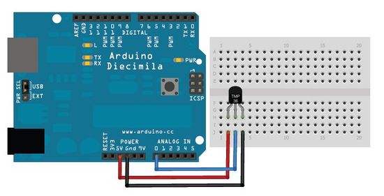
Unlike the FSR or photocell sensors we have looked at, the TMP36 and friends doesn't act like a resistor. Because of that, there is really only one way to read the temperature value from the sensor, and that is plugging the output pin directly into an Analog (ADC) input.
Remember that you can use anywhere between 2.7V and 5.5V as the power supply. For this example I'm showing it with a 5V supply but note that you can use this with a 3.3v supply just as easily. No matter what supply you use, the analog voltage reading will range from about 0V (ground) to about 1.75V.
If you're using a 5V Arduino, and connecting the sensor directly into an Analog pin, you can use these formulas to turn the 10-bit analog reading into a temperature:
Voltage at pin in milliVolts = (reading from ADC) * (5000/1024)
This formula converts the number 0-1023 from the ADC into 0-5000mV (= 5V)
If you're using a 3.3V Arduino, you'll want to use this:
Voltage at pin in milliVolts = (reading from ADC) * (3300/1024)
This formula converts the number 0-1023 from the ADC into 0-3300mV (= 3.3V)
Then, to convert millivolts into temperature, use this formula:
Centigrade temperature = [(analog voltage in mV) - 500] / 10
Un thermomètre simple
This example code for Arduino shows a quick way to create a temperature sensor, it simply prints to the serial port what the current temperature is in both Celsius and Fahrenheit.
    //TMP36 Pin Variables
    int sensorPin = 0; //the analog pin the TMP36's Vout (sense) pin is connected to
    //the resolution is 10 mV / degree centigrade with a
    //500 mV offset to allow for negative temperatures
    /*
    * setup() - this function runs once when you turn your Arduino on
    * We initialize the serial connection with the computer
    */
    void setup()
    {
    Serial.begin(9600); //Start the serial connection with the computer
    //to view the result open the serial monitor
    }
    void loop() // run over and over again
    {
    //getting the voltage reading from the temperature sensor
    int reading = analogRead(sensorPin);
    // converting that reading to voltage, for 3.3v arduino use 3.3
    float voltage = reading * 5.0;
    voltage /= 1024.0;
    // print out the voltage
    Serial.print(voltage); Serial.println(" volts");
    // now print out the temperature
    float temperatureC = (voltage - 0.5) * 100 ; //converting from 10 mv per degree wit 500 mV offset
    //to degrees ((volatge - 500mV) times 100)
    Serial.print(temperatureC); Serial.println(" degrees C");
    // now convert to Fahrenheight
    float temperatureF = (temperatureC * 9.0 / 5.0) + 32.0;
    Serial.print(temperatureF); Serial.println(" degrees F");
    delay(1000); //waiting a second
    }
Obtenir une meilleure précision
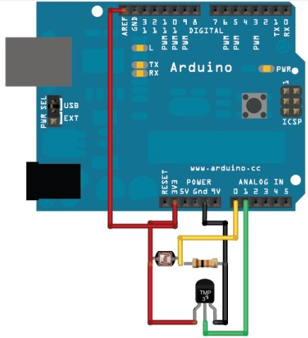
For better results, using the 3.3v reference voltage as ARef instead of the 5V will be more precise and less noisy
This example from the light&temp datalogging tutorial has a photocell but you can ignore it
| To use the 3.3v pin as your analog reference, don't forget to specify "analogReference(EXTERNAL)" in your setup as in the code below. |
    /* Sensor test sketch
    for more information see http://www.ladyada.net/make/logshield/lighttemp.html
    */
    #define aref_voltage 3.3 // we tie 3.3V to ARef and measure it with a multimeter!
    //TMP36 Pin Variables
    int tempPin = 1; //the analog pin the TMP36's Vout (sense) pin is connected to
    //the resolution is 10 mV / degree centigrade with a
    //500 mV offset to allow for negative temperatures
    int tempReading; // the analog reading from the sensor
    void setup(void) {
    // We'll send debugging information via the Serial monitor
    Serial.begin(9600);
    // If you want to set the aref to something other than 5v
    analogReference(EXTERNAL);
    }
    void loop(void) {
    tempReading = analogRead(tempPin);
    Serial.print("Temp reading = ");
    Serial.print(tempReading); // the raw analog reading
    // converting that reading to voltage, which is based off the reference voltage
    float voltage = tempReading * aref_voltage;
    voltage /= 1024.0;
    // print out the voltage
    Serial.print(" - ");
    Serial.print(voltage); Serial.println(" volts");
    // now print out the temperature
    float temperatureC = (voltage - 0.5) * 100 ; //converting from 10 mv per degree wit 500 mV offset
    //to degrees ((volatge - 500mV) times 100)
    Serial.print(temperatureC); Serial.println(" degrees C");
    // now convert to Fahrenheight
    float temperatureF = (temperatureC * 9.0 / 5.0) + 32.0;
    Serial.print(temperatureF); Serial.println(" degrees F");
    delay(1000);
    }
Source: AdaFruit
Traduit avec l'autorisation d'AdaFruit Industries - Translated with the permission from Adafruit Industries - www.adafruit.com
Toute référence, mention ou extrait de cette traduction doit être explicitement accompagné du texte suivant : « Traduction par MCHobby (www.MCHobby.be) - Vente de kit et composants » avec un lien vers la source (donc cette page) et ce quelque soit le média utilisé.
L'utilisation commercial de la traduction (texte) et/ou réalisation, même partielle, pourrait être soumis à redevance. Dans tous les cas de figures, vous devez également obtenir l'accord du(des) détenteur initial des droits. Celui de MC Hobby s'arrêtant au travail de traduction proprement dit.
