Différences entre versions de « Spark-Core-LED »
| Ligne 12 : | Ligne 12 : | ||
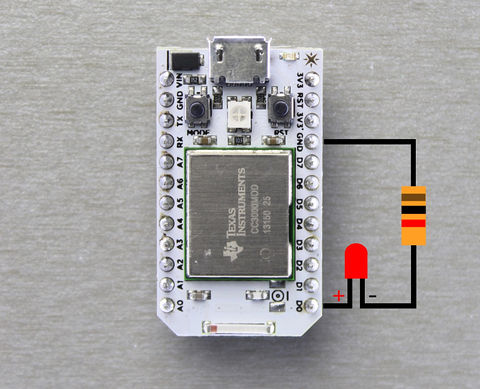
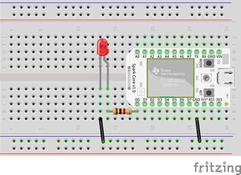
Connect everything together as shown in the picture. The LED is connected to pin D0 of the Core. The positive (longer pin) of the LED is connected to D0 via a resistor and its negative pin (shorter) is connected to ground. | Connect everything together as shown in the picture. The LED is connected to pin D0 of the Core. The positive (longer pin) of the LED is connected to D0 via a resistor and its negative pin (shorter) is connected to ground. | ||
| + | {{SPARKImage|Spark.IO-Core-LED-00.jpg|480px}} | ||
| + | |||
| + | {{SPARKImage|Spark.IO-Core-LED-01.jpg|480px}} | ||
| + | |||
| + | == Valeur de la résistance == | ||
| + | |||
| + | But wait, what's the value of the resistor again? | ||
| + | |||
| + | ''Here's how we find that out:'' | ||
| + | |||
| + | According to [http://fr.wikipedia.org/wiki/Loi_d%27Ohm Ohm's Law] : Voltage = Current x Resistance | ||
| + | |||
| + | Therefore, Resistance = Voltage/ Current | ||
| + | |||
| + | In our case, the output voltage of the Core is 3.3V but the LED (typically) has a forward voltage drop of around 2.0V. So the actual voltage would be: | ||
| + | |||
| + | 3.3V - 2.0V = 1.3V | ||
| + | |||
| + | The required current to light up an LED varies any where between 2mA to 20mA. More the current, brighter the intensity. But generally its a good idea to drive the LED at a lower limit to prolong its life span. We will choose a drive current of 5mA. | ||
| + | |||
| + | Hence, Resistance = 1.3V/ 5mA = 260 Ohms | ||
| + | |||
| + | {{underline|Note:}} | ||
| + | |||
| + | Since there is so much variation in the values of the forward voltage drop of the LEDs depending upon type, size, color, manufacturer, etc., you could successfully use a resistor value from anywhere between 220Ohms to 1K Ohms. | ||
| + | |||
| + | In the picture above, we used a 1K resistor (Brown Black Red) | ||
{{Spark-Core-Hacking-TRAILER}} | {{Spark-Core-Hacking-TRAILER}} | ||
Version du 24 novembre 2014 à 21:14
|
|
En cours de traduction/élaboration. |
Faire clignoter une LED
Blinking an LED is the "Hello World" example of the microcontroller world. It's a nice way to warm up and start your journey into the land of embedded hardware.
For this example, you will need a Spark Core (duh!), a Breadboard, an LED, a Resistor (we will soon find out a suitable value) and a USB cable.
Brancher
Connect everything together as shown in the picture. The LED is connected to pin D0 of the Core. The positive (longer pin) of the LED is connected to D0 via a resistor and its negative pin (shorter) is connected to ground.

Crédit: Particle.IO www.particle.io

Crédit: Particle.IO www.particle.io
Valeur de la résistance
But wait, what's the value of the resistor again?
Here's how we find that out:
According to Ohm's Law : Voltage = Current x Resistance
Therefore, Resistance = Voltage/ Current
In our case, the output voltage of the Core is 3.3V but the LED (typically) has a forward voltage drop of around 2.0V. So the actual voltage would be:
3.3V - 2.0V = 1.3V
The required current to light up an LED varies any where between 2mA to 20mA. More the current, brighter the intensity. But generally its a good idea to drive the LED at a lower limit to prolong its life span. We will choose a drive current of 5mA.
Hence, Resistance = 1.3V/ 5mA = 260 Ohms
Note:
Since there is so much variation in the values of the forward voltage drop of the LEDs depending upon type, size, color, manufacturer, etc., you could successfully use a resistor value from anywhere between 220Ohms to 1K Ohms.
In the picture above, we used a 1K resistor (Brown Black Red)
Source: Particle Core Examples créé par Particle.IO.
Traduction (et augmentation de contenu) réalisée par Meurisse D pour MCHobby.be - Translated (and enhanced) by Meurisse D. for MCHobby.be
Traduit avec l'autorisation de Particle.IO - Translated with the permission from Particle.IO - Particle.IO
Toute référence, mention ou extrait de cette traduction doit être explicitement accompagné du texte suivant : « Traduction par MCHobby (www.MCHobby.be) - Vente de kit et composants » avec un lien vers la source (donc cette page) et ce quelque soit le média utilisé.
L'utilisation commercial de la traduction (texte) et/ou réalisation, même partielle, pourrait être soumis à redevance. Dans tous les cas de figures, vous devez également obtenir l'accord du(des) détenteur initial des droits. Celui de MC Hobby s'arrêtant au travail de traduction proprement dit.