Différences entre versions de « RASP-SENSE-HAT-ASTRO-PI-Bouton »
| Ligne 9 : | Ligne 9 : | ||
[[Fichier:RASP-SENSE-HAT-ASTRO-PI-Bouton-01.jpg]] | [[Fichier:RASP-SENSE-HAT-ASTRO-PI-Bouton-01.jpg]] | ||
| + | |||
| + | == Les éléments nécessaires == | ||
| + | In order to do this you will need access to the following items: | ||
| + | |||
| + | * A breadboard | ||
| + | * 6 tactile push buttons | ||
| + | * 14 male to female jumper cables | ||
| + | * A 40 pin GPIO stacking header (with the long pins) | ||
| + | |||
| + | Use this to mount the Sense HAT onto the Raspberry Pi instead of the one you received with the HAT. Then you'll have the GPIO pins protruding through the HAT such that jumper cables can be attached to the breadboard. | ||
| + | |||
| + | == Le connecteur GPIO == | ||
| + | The buttons are wired to the last six pins at the bottom of the GPIO header pins on the Pi. | ||
| + | |||
| + | Voici comment les raccorder sur le connecteur GPIO. | ||
| + | |||
| + | [[Fichier:RASP-SENSE-HAT-ASTRO-PI-Bouton-02.png]] | ||
| + | |||
| + | Note the orientation of the pin diagram is with the Ethernet and USB ports facing downwards, and the row of pins on the right hand side of the Pi. | ||
| + | |||
| + | This means that this setup cannot be exactly replicated if you're using an old model A or B Pi. If you are using an older model you can choose other pins, but be sure to modify the pin numbering in your code so that it will work on a flight unit before you submit via the competition website. | ||
| + | |||
| + | These are the pin assignments: | ||
| + | |||
| + | * Les quatres boutons supérieurs: | ||
| + | ** UP: GPIO 26, pin 37 | ||
| + | ** DOWN: GPIO 13, pin 33 | ||
| + | ** LEFT: GPIO 20, pin 38 | ||
| + | ** RIGHT: GPIO 19, pin 35 | ||
| + | * Bottom pair | ||
| + | ** A (left): GPIO 16, pin 36 | ||
| + | ** B (right): GPIO: 21, pin 40 | ||
| + | |||
| + | If you use these buttons in your Astro Pi competition entry, then you will need to comply with these pin assignments in order for your code to work on the flight hardware that Tim Peake will have on the ISS. | ||
| + | |||
| + | == Détecter un bouton == | ||
| + | Voici comment détecter la pression sur un bouton. | ||
| + | |||
| + | GPIO pins can be set up as an input or an output. Output mode is used when you want to supply voltage to a device like an LED or buzzer. With input mode, a GPIO pin has a value that we can read in our code. If the pin has voltage going into it, the reading would be 1 ({{fname|HIGH}}, le niveau haut); if the pin was connected directly to ground (no voltage), the reading would be 0 ({{fname|LOW}}, le niveau bas). | ||
| + | |||
| + | The goal is to use a push button to switch voltage on and off for a GPIO pin, thus making the pin's reading change in our code when we press the button. | ||
| + | |||
| + | When a GPIO pin is in input mode the pin is said to be '''floating''', meaning that it has no fixed voltage level. That's no good for what we want, as the pin will randomly float between {{fname|HIGH}} and {{fname|LOW}}. For this job, we need to know categorically whether the button is up or down, so we need to fix the voltage level to {{fname|HIGH}} or {{fname|LOW}}, and then make it change only when the button is pressed. | ||
| + | |||
| + | The flight hardware buttons are all wired in a '''pull up''' configuration, which means we pull the GPIO to {{fname|HIGH}} and only short it to {{fname|LOW}} when we press the button.o | ||
| + | |||
| + | [[fichier:RASP-SENSE-HAT-ASTRO-PI-Bouton-03.png]] | ||
{{RASP-SENSE-HAT-ASTRO-PI-TRAILER}} | {{RASP-SENSE-HAT-ASTRO-PI-TRAILER}} | ||
Version du 22 octobre 2015 à 18:31
|
|
En cours de traduction/élaboration. |
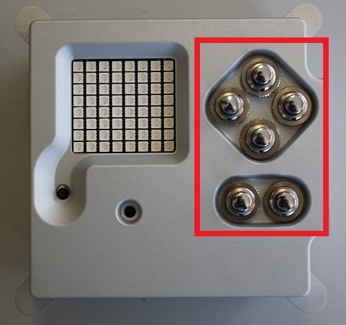
Boutons de vols
Le boîtier de vol de l'Astro Pi utilise le sense Hat ainsi que 6 boutons d'usage général, boutons que vous pourriez brancher sur le GPIO du Raspberry Pi. Cela demande quelques opérations de bricolages mais au final, vous auriez 6 boutons de plus branché sur votre Pi, des boutons que vous pourriez exploiter dans vos propres programmes.
Il s'agit de simple bouton poussoir que l'on branche directement sur les broches du GPIO (dans un circuit pull-up): vous pouvez facilement recréer cette configuration en utilisant un breadboard, quelques boutons et du fils.
Les éléments nécessaires
In order to do this you will need access to the following items:
- A breadboard
- 6 tactile push buttons
- 14 male to female jumper cables
- A 40 pin GPIO stacking header (with the long pins)
Use this to mount the Sense HAT onto the Raspberry Pi instead of the one you received with the HAT. Then you'll have the GPIO pins protruding through the HAT such that jumper cables can be attached to the breadboard.
Le connecteur GPIO
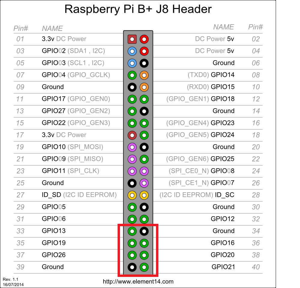
The buttons are wired to the last six pins at the bottom of the GPIO header pins on the Pi.
Voici comment les raccorder sur le connecteur GPIO.
Note the orientation of the pin diagram is with the Ethernet and USB ports facing downwards, and the row of pins on the right hand side of the Pi.
This means that this setup cannot be exactly replicated if you're using an old model A or B Pi. If you are using an older model you can choose other pins, but be sure to modify the pin numbering in your code so that it will work on a flight unit before you submit via the competition website.
These are the pin assignments:
- Les quatres boutons supérieurs:
- UP: GPIO 26, pin 37
- DOWN: GPIO 13, pin 33
- LEFT: GPIO 20, pin 38
- RIGHT: GPIO 19, pin 35
- Bottom pair
- A (left): GPIO 16, pin 36
- B (right): GPIO: 21, pin 40
If you use these buttons in your Astro Pi competition entry, then you will need to comply with these pin assignments in order for your code to work on the flight hardware that Tim Peake will have on the ISS.
Détecter un bouton
Voici comment détecter la pression sur un bouton.
GPIO pins can be set up as an input or an output. Output mode is used when you want to supply voltage to a device like an LED or buzzer. With input mode, a GPIO pin has a value that we can read in our code. If the pin has voltage going into it, the reading would be 1 (HIGH, le niveau haut); if the pin was connected directly to ground (no voltage), the reading would be 0 (LOW, le niveau bas).
The goal is to use a push button to switch voltage on and off for a GPIO pin, thus making the pin's reading change in our code when we press the button.
When a GPIO pin is in input mode the pin is said to be floating, meaning that it has no fixed voltage level. That's no good for what we want, as the pin will randomly float between HIGH and LOW. For this job, we need to know categorically whether the button is up or down, so we need to fix the voltage level to HIGH or LOW, and then make it change only when the button is pressed.
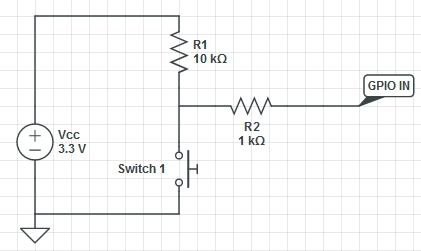
The flight hardware buttons are all wired in a pull up configuration, which means we pull the GPIO to HIGH and only short it to LOW when we press the button.o
Source: Getting Started with Astro PI et Astro-Pi Guide proposé par Raspberry Pi Learning Resource (www.raspberrypi.org)
Licence Creative Commons - CC-BY-SA
The learning resource is provided for free by the Raspberry Pi Foundation under a Creative Commons licence.
Find more at raspberrypi.org/resources and github.com/raspberrypilearning.
Crédit de traduction: Toute référence, mention ou extrait de cette traduction doit également être explicitement accompagné du crédit de traduction suivant : « Traduction par MCHobby (shop.MCHobby.be) » avec un lien vers la source (donc cette page) et ce quelque soit le média utilisé.


