RASP-SENSE-HAT-ASTRO-PI-Mouvement
Senseur de mouvement
|
|
En cours de traduction/élaboration. |
Le Sense HAT met en oeuvre de nombreux senseurs, l'un d'eux est un senseur de mouvement appelé IMU. L'IMU est capable de mesurer le type de mouvement qu'il subit.
La source anglaise de cette traduction se trouve ici https://www.raspberrypi.org/learning/astro-pi-guide/sensors/movement.md
Qu'est ce qu'un IMU?
Il est équipé d'une centrale de mesure inertielle (dite IMU pou Inertial Measurement Unit) sous forme d'une puce qui inclus:
- Un gyroscope (qui mesure le moment et la rotation)
- Un accéléromètre (qui mesure les forces d'accélération et peut être utilisé pour trouver la direction de la gravité)
- Un magnétomètre (qui mesure le champ magnétique de la terre, c'est un peu comme une boussole)
Why is a movement sensor important, though? When you're up in space there is one question of absolute importance to which you must always know the answer: which way am I pointing?
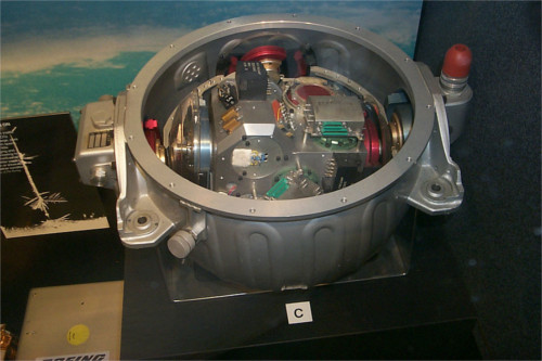
If you don't know your orientation you are in big trouble, so an IMU sensor like this one is used on all manned and unmanned spacecraft to track movements and maintain an understanding of orientation. Even the earliest spacecraft had them. Ask your grandparents if they remember the Apollo missions (wikipedia, anglais) that landed humans on the surface of the moon.
Above is a picture of the IMU sensor from the Apollo command module. You'll notice how big it is compared to the tiny black cube on the Astro Pi; that's the difference between 1975 and 2015 technology. Incidentally, the Astro Pi IMU is probably not as accurate as the Apollo one, however it is a million times cheaper!
Comment l'orientation est elle représentée?
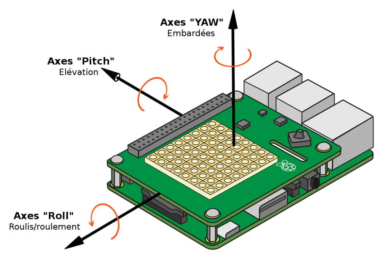
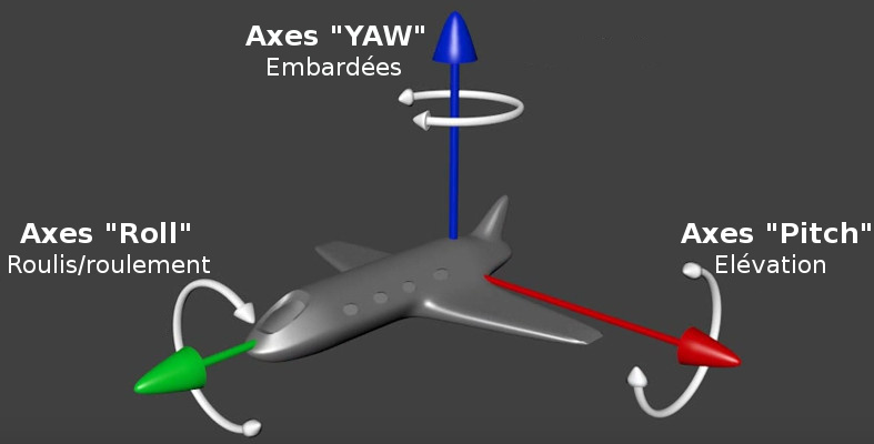
Nous savons que la terre tourne autour d'un axe qui va du pôle Nord vers le pôle Sud. Tous les objets (y compris dans l'espace) ont 3 axes autour desquels ils peuvent tourner. Si vous savez déterminer la quantité de "rotation" sur chacun de ces axes alors vous savez aussi vers où l'objet pointe.
Les 3 axes utilisés pour décrire le mouvement sont:
- Elévation, dit "Pitch" en anglais (comme quand l'avion décolle)
- Roulis/Roulement, dit "Roll" en anglais (comme un avion qui faire la rouleau de la victoire, ou une voiture qui fait un tonneau)
- Lacet/Embardée, dit "Yaw" en anglais (imaginez un avion qui dévie de sa route comme le ferait une voiture, où une voiture qui prend un virage "en lacet")
Etant donné que l'interface de programmation du Sense Hat utilise ces mêmes mots clés en anglais pour vous permettre d'accéder aux valeurs, nous allons préserver les termes "Pitch"n "Roll", "Yaw".
Les images ci-dessus montre les 3 axes en relation avec le Sense Hat ainsi que la correspondance dans le monde réel.
Nous allons maintenant démarrer le programme d'exemple en 3D.
Démonstration Appolo Soyuz
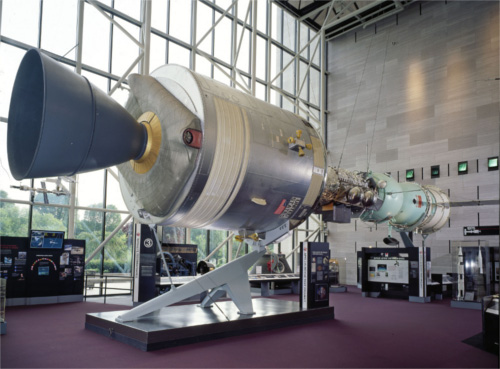
The image below shows the Apollo Soyuz module that was used to take humans to the surface of the moon during the 1970s. The 3D demo we're going to play with shows this same spacecraft (but with less detail).
You will need to have your Raspberry Pi and Sense HAT connected to the internet in order to download the required software.
Enter the commands below into a terminal window:
sudo apt-get install python3-pip
sudo pip-3.2 install pi3d
git clone git://github.com/astro-pi/apollo-soyuz
cd apollo-soyuz
sudo ./soyuz.py
Pi 1 users will have to wait 3 to 4 minutes for this to load. For Pi 2 users it's about 30 seconds. When you see the spacecraft appear on the screen start moving the Raspberry Pi and Sense HAT around with your hands. The the main booster is where the SD card slot is on your Pi.
See if you can get the spacecraft to do the pitch, roll and yaw movements. Refer back to the video (YouTube, anglais) if you need to remind yourself which is which.
The code behind this demo is basically calling the Sense HAT get_orientation function which accesses the IMU sensor. This then returns three angles between 0 and 360 degrees, one for each axis (pitch, roll and yaw). The spacecraft model is then rotated by those angles so that it points in the same direction. This is all repeating over and over very quickly to maintain the orientation of the model with what the IMU is reporting.
Press Esc to exit the demo. Let's try a simpler version of this ourselves in code.
Quelle direction est-elle pointée?
1. Open Python 3 from a terminal window as sudo by typing:
sudo idle3 &
2. Select File > New Window (Fichier > Nouvelle fenêtre) and enter the following code:
from sense_hat import SenseHat
sense = SenseHat()
sense.clear()

o = sense.get_orientation()
pitch = o["pitch"]
roll = o["roll"]
yaw = o["yaw"]
print("pitch %s roll %s yaw %s" % (pitch, roll, yaw))
3. Select File > Save (Fichier > Sauver sous) and choose a file name for your program.
4. Select Run > Run module (Executer > Exécuter module).
5. If you see the error IMU Init Failed, please run as root / use sudo on the last line in red, it means you haven't followed the instructions above. Close everything and go back to step 1.
Le message "IMU Init Failed" signifie "Echec d'initialisation de l'IMU".
6. You should now see something like this:
IMU Init Succeeded
pitch 356.35723002363454 roll 303.4986602798494 yaw 339.19880231669873
La première ligne "IMU Init Succeeded" signifie que l'IMU à été initialisé avec succès.
7. We don't need all the numbers after the decimal point so let's round them off. Just before the print("pitch %s roll %s yaw %s" % (pitch, roll, yaw)) line, add these lines below:
pitch = round(pitch, 1)
roll = round(roll, 1)
yaw = round(yaw, 1)
Surveiller les mouvements
It would be good to monitor the axis values changing during movements, so let's put your code into a while loop and run it again:
while True:
   o = sense.get_orientation()
   pitch = o["pitch"]
   roll = o["roll"]
   yaw = o["yaw"]

   pitch = round(pitch, 1)
   roll = round(roll, 1)
   yaw = round(yaw, 1)

   print("pitch %s roll %s yaw %s" % (pitch, roll, yaw))
Move the Pi around in your hand and you should see the numbers changing. See if you can just make one axis change by moving only in the pitch direction for example. Do this for all three axes. Press Ctrl - C to stop the program.
Afficher l'orientation sur la matrice LED
1. Displaying something which is 3D in a 2D way is always a challenge, especially when your screen is only 8 x 8 pixels in size. One way which might work well is to have one LED for each axis and then make them move in different ways. For example:
- The pitch LED (élévation) could go up and down
- The roll LED (roulis, roulement) could go side to side
- The yaw LED (embardée) could chase around the edge
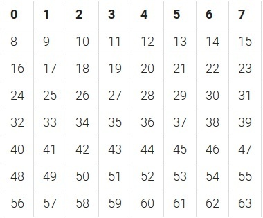
2. Here is a clever trick you can do. The table below shows the sequential LED numbers laid out in horizontal rows.
For any of those numbers you can convert them into their X Y coordinate using the code below.
y = number // 8
x = number % 8
For the y value you floor divide // the number by 8. This is integer division and ignores the remainder. Then for the x value you do the modulus % of 8 which gives you only the remainder.
For example (using the number 60 which is on the bottom row):
60 // 8 = 7
60 % 8 = 4
3. Try this code:
number = 60

y = number // 8
x = number % 8

sense.set_pixel(x, y, 255, 255, 255)
4. The clever trick is to make a list containing the LED numbers for the path you want it to move back and forth through. So say you want to make an LED chase around the edge you would read the numbers accross the top of the table, down the right hand side, backwards along to bottom and up the left side. So it would be:
edge = [0, 1, 2, 3, 4, 5, 6, 7, 15, 23, 31, 39, 47, 55, 63, 62, 61, 60, 59, 58, 57, 56, 48, 40, 32, 24, 16, 8]
We can then find the length of the list using the len function:
length = len(edge)
So the length is 28. If we divide 28 by 360 we have a ratio between, say, the yaw measurement and the positions in our list (how far around the edge we are). We can then get the sequential pixel number out of the list at the calculated position, work out its coordinate and then switch the LED on! Like this:
from sense_hat import SenseHat

sense = SenseHat()
sense.clear()

edge = [0, 1, 2, 3, 4, 5, 6, 7, 15, 23, 31, 39, 47, 55, 63, 62, 61, 60, 59, 58, 57, 56, 48, 40, 32, 24, 16, 8]
length = len(edge)
ratio = length / 360.0

while True:
    o = sense.get_orientation()
    pitch = o["pitch"]
    roll = o["roll"]
    yaw = o["yaw"]

    yaw_list_position = int(yaw * ratio)

    yaw_pixel_number = edge[yaw_list_position]

    y = yaw_pixel_number // 8
    x = yaw_pixel_number % 8

    sense.set_pixel(x, y, 255, 255, 255)
5. What you'll notice is that the above code only turns LEDs on, you'll need to figure out how to turn them off yourself. Try having a variable for the previous x and y from the last time around the loop and if this is different from the new x and y you use set_pixel to set the LED to black/éteinte.
Source: Getting Started with Astro PI et Astro-Pi Guide proposé par Raspberry Pi Learning Resource (www.raspberrypi.org)
Licence Creative Commons - CC-BY-SA
The learning resource is provided for free by the Raspberry Pi Foundation under a Creative Commons licence.
Find more at raspberrypi.org/resources and github.com/raspberrypilearning.
Crédit de traduction: Toute référence, mention ou extrait de cette traduction doit également être explicitement accompagné du crédit de traduction suivant : « Traduction par MCHobby (shop.MCHobby.be) » avec un lien vers la source (donc cette page) et ce quelque soit le média utilisé.
