Spark-Core-Brochage
|
|
En cours de traduction/élaboration. |
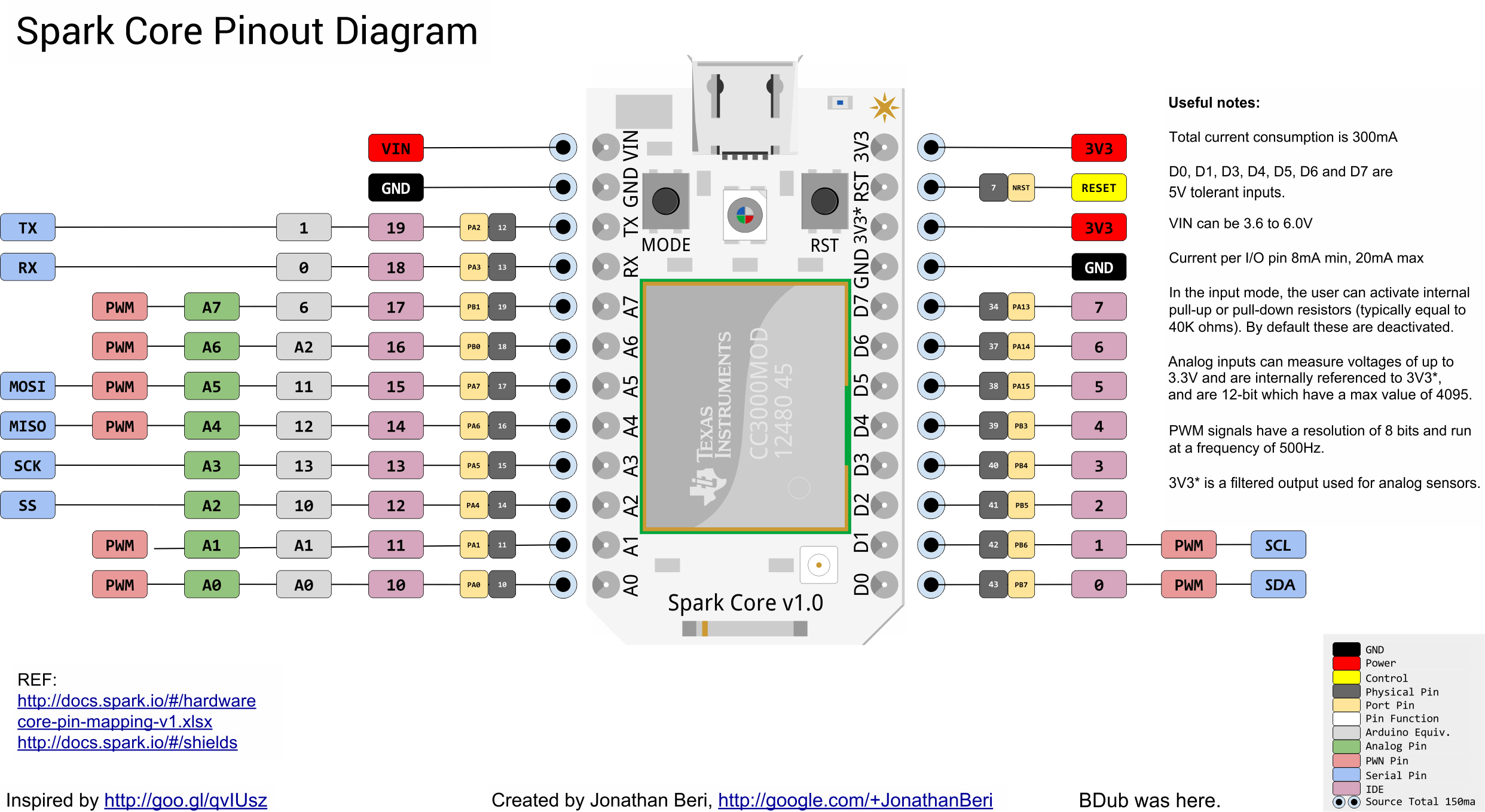
Diagramme

Crédit: Particle.IO www.particle.io
Vous pouvez également obtenir ce diagramme directement depuis le site de Spark Core (png).
Introduction
The Spark Core offers a total 18 I/O pins to the user: D0 to D7, A0 to A7 and two pins that are preset to serial - TX and RX.
| All of these I/O pins run at 3.3V and the user should keep this in mind before attaching any external peripherals to them. The only exception to this are the following pins that are tolerant to 5V inputs: D0, D1, D3, D4, D5, D6 and D7 |
Broches digitals
Each pin on the Core can either be configured as input (with or without pull-up or pull-down) or as output (push-pull or open-drain) using the pinMode() function.
After setting them up, the user can then write to or read from the pins using digitalWrite() and digitalRead() functions respectively.
Each of these pins can individually source/sink a maximum of 20mA. In the input mode, the user can activate internal pull-up or pull-down resistors (typically equal to 40K ohms). By default these are deactivated.
Entrées analogiques
Pins A0 to A7 can be set up as analog inputs and can measure voltages of upto 3.3V and are internally referenced to VDD. The user can read the pins using analogRead() function which returns a 12bit value.
Sorties PWM
Aussi appelées sorties analogiques.
This term is misleading and misused but is widely adopted in the Arduino community. The pins that are set to output an analog value don't actually output an analog voltage but rather produce a PWM signal whose duty cycle can be varied thus varying the total average power of the signal. On the Core, the PWM signals have a resolution of 8 bits and run at a frequency of 500Hz.
Having said that, the user can send analog values to the pins using the function analogWrite().
This feature is only available on the following pins: A0, A1, A4, A5, A6, A7, D0 et D1.
Ports séries (UART)
The Core features three serial ports.

Crédit: Particle.IO www.particle.io
The first one is a CDC (Communications Device Class) available over the USB port. When configured, it will show up as a virtual COM port on the computer. (usage: Serial.begin(9600);)
The second one is a hardware USART available via the TX and RX pins on the Core. (usage: Serial1.begin(9600);)
The third one is a hardware USART available via the D1(Tx) and D0(Rx) pins on the Core. (usage: Serial2.begin(9600);)
Configuration and use of all of these serial ports is described in the serial functions (Spark, anglais).
| Please take into account that the voltage levels on these pins runs at 0V to 3.3V and should not be connected directly to a computer's RS232 serial port which operates at +/- 12V and can damage the Core. |
Bus SPI
The Serial Peripheral Interface is available on pins:
- A2: SS (Slave Select)
- A3: SCK (Serial Clock)
- A4: MISO (Master In Slave Out)
- A5: MOSI (Master Out Slave In)

Crédit: Particle.IO www.particle.io
NOTE: All of these pins run at 3.3V logic levels.
Bus I2C
I2C communication pins are multiplexed with the standard GPIO pins D0 and D1.
- D0: SDA (Serial Data Line)
- D1: SCL (Serial Clock)

Crédit: Particle.IO www.particle.io
Both of these pins run at 3.3V logic level but are tolerant to 5V inputs.
Connecteur JTAG
In addition to having the ability to load new firmware over USB and WiFi, the users also have direct access to the STM32 chip via the JTAG channel. In order to do this, you will need a JTAG shield and a JTAG programmer. You could make your own JTAG shield or buy one from us. Currently we have only tested the ST-LINK/V2 (st.com, anglais) programmer successfully.

Crédit: Particle.IO www.particle.io
The hardware files for the JTAG shield are available here (Spark, GitHub, Anglais).
Source: Particle Core Hardware créé par Particle.IO.
Traduction réalisée par Meurisse D pour MCHobby.be - Translated by Meurisse D. for MCHobby.be
Traduit avec l'autorisation de Spark.IO - Translated with the permission from Particle.IO - Particle.IO
Toute référence, mention ou extrait de cette traduction doit être explicitement accompagné du texte suivant : « Traduction par MCHobby (www.MCHobby.be) - Vente de kit et composants » avec un lien vers la source (donc cette page) et ce quelque soit le média utilisé.
L'utilisation commercial de la traduction (texte) et/ou réalisation, même partielle, pourrait être soumis à redevance. Dans tous les cas de figures, vous devez également obtenir l'accord du(des) détenteur initial des droits. Celui de MC Hobby s'arrêtant au travail de traduction proprement dit.