Différences entre versions de « Adafruit GPS ULTIMATE »
(→Source) |
|||
| Ligne 201 : | Ligne 201 : | ||
First, we should try getting the logger to run.Open up the '''File→Examples→Adafruit_GPS→locus_start''' sketch. This will demonstrate how to start the logger (called LOCUS) | First, we should try getting the logger to run.Open up the '''File→Examples→Adafruit_GPS→locus_start''' sketch. This will demonstrate how to start the logger (called LOCUS) | ||
| − | {{tmbox| | + | {{tmbox|A suivre...}} |
| − | |||
== Source == | == Source == | ||
Version du 8 mai 2012 à 11:40
|
|
En cours de traduction |
Introduction
http://ladyada.net/products/ultimategps/
Raccorder au PC
Les modules GPS sont vraiment merveilleux, dès qu'ils sont allumés ils essayent de se synchroniser (FIX) et produisent des données. Comme presques tous les GPS existants, Le GPS Ultimate d'Adafruit utilise une logique TTL sur sa sortie série pour envoyer ses données.
La meilleure façon de commencer à tester un GPS est de le brancher directement sur un ordinateur par l'intermédiaire du convertisseur Série TTL vers USB d'un Arduino.
Vous pouvez aussi utiliser un adaptateur FTDI ou tout autre adaptateur TTL mais dans cette démonstration nous allons utiliser un simple Arduino.
Le code
Pour commencer, charger un sketch "blanc" dans votre Arduino:
// Ce sketch vous permet de by-passer l'Atmega
// et de connecter des senseurs (comme un GPS ou lecteur d'empreinte)
// directement sur le convertisseur USB/Série de votre carte
// Arduino.

// Connecter VIN au +5V
// Connecter GND à la masse/ground
// Connecter GPS RX (réception donnée dans le GPS) vers Arduino Pin 0 (digitiale)
// Connecter GPS TX (sortie de donnée du GPS) vers Arduino Pin 1 (digitiale)

void setup() {}
void loop() {}
Voici comment contourner la puce ATMega, vous vous raccordez directement sur le convertisseur USB/Serial.
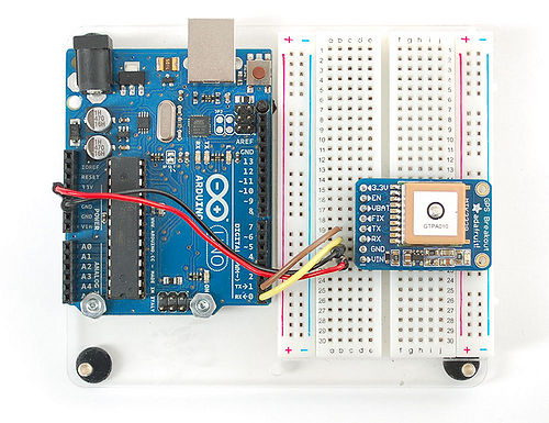
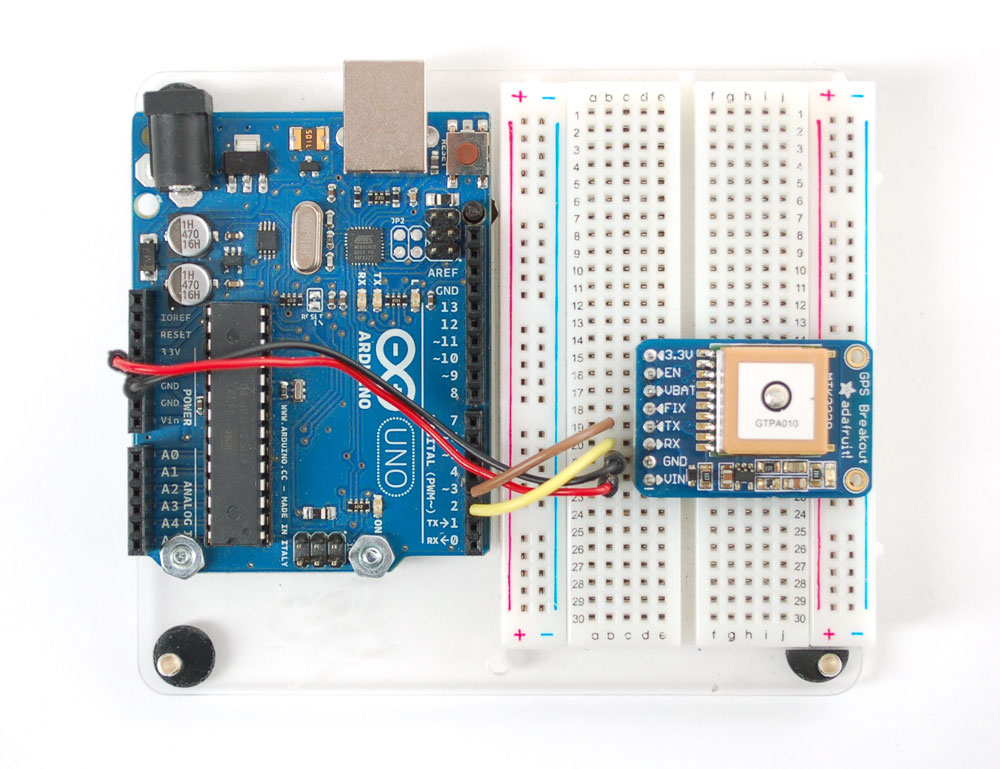
Une fois que vous avez chargé le scketch, raccordez le GPS comme suit:
Le montage
Messages GPS
Branchez ensuite le cable USB et ouvrez le moniteur Serie d'Arduino IDE. Veillez à sélectionner 9600 baud dans la liste déroulante.
Vous verrez alors apparaître un texte fort semblable à ce qui suit:
Ce que vous voyez sont les "messages NMEA" brutes que le module produit.
Il y a différents types de messages NMEA, les messages les plus couramment utilisés sont:
- $GPRMC - Global Positioning Recommended Minimum Coordinates
- $GPGGA
Ces deux messages produisent les informations suivantes:
- temps,
- date,
- latitude,
- longitude,
- altitude,
- Vitesse estimé (au sol),
- Type de FIX (synchronisation).
Le type de Fix indique si le GPS est synchronisé sur des satellites et s'il reçoit assez de données pour déterminer la position (2D fix) ou la position+altitude (3D fix).
Pour plus d'information sur les messages NMEA et ce qu'ils contiennent, vous pouvez vous documenter sur le site suivant www.gpsinformation.org/dale/nmea.htm
Si vous prenez attention au contenu de la capture présentée ci-dessus, vous pouvez constater qu'il y a beaucoup de virgules (sans données en elles).
C'est parce que le module est sur un bureau, à l'intérieur, et qu'il n'est pas synchronisé (pas de FIX).
Pour que le module se synchronise, il faut qu'il soit à l'extérieur.
| Les modules GPS vont toujours envoyer des données MEME S'ILS N'ONT PAS DE SYNCHRONISATION!
Afin d'obtenir des donnée 'valides' (remplies) vous devez placer le module GPS directement à l'extérieur avec l'antenne carrée en céramique pointant vers le ciel. |
Interprétation des résultats - Coordonnées
Regardez la ligne mentionnant $GPRMC,194509.000,A,4042.6142,N,07400.4168,W,2.03,221.11,160412,,,A*77
Cette ligne est appelée une phrase RMC (Recommended Minimum) contenant les information minimale et contient déjà plein d'information utiles. Chaque donnée est séparée des autre par une virgule (comma en anglais).
La première partie 194509.000 est une indication de temps GMT. Les deux premiers chiffres 19 indique l'heure (19:00h, aussi connu comme 7pm ou 7 heures du soir) et les deux suivants indique les minutes, ensuite deux autres chiffres pour les secondes et finallement les millisecondes. Donc, cette capture a eu lieu à 7:45 pm (après midi) et 9 secondes (ou encore à 19:45:09 en notation 24h au format européen).
La seconde partie est un 'code statut' (status code), à savoir:
- V pour "Void" indique que les données sont invalides.
- A pour "Active" indique que le GPS peut obtenir un e synchronisation (lock/fix)
Les 4 données suivantes contiennent des données de géolocalisation.
- La Latitude (première série d'information) correspond à l'axe Sud -> Nord (Truc pour Google Map: le Sud vers le bas est négatif, le nord vers le Haut est positif)
- La Longitude (deuxième série d'information) correspond à l'axe Ouest -> Est (Truc pour Google Map: De gauche droite vers l'écriture... on ajoute des lettres sur la lignes. Ouest est négatif, Est est positif)
Dans cet exemple, la position est 4042.6142,N (Latitude 40 degrés, 42.3932 minutes North [Nord]) et 07400.4168,W (Longitude 74 degrés, 0.4680 minutes West [ouest]).
Localisation sur Google Maps
Pour identifier cette localisation sur Google Maps, tapez +40° 42.6142', -74° 00.4168' dans la zone de recherche de Google Maps.
Malheureusement, Google Maps n'accepte pas directement la notation ENMA, vous devez donc utiliser +/- à la place de la notation NSWE. N (Nord) et E (Est) sont positifs, S (Sud) et W (Ouest=West) sont négatif.
Interprétation des résultats - Vitesse
En reprenant notre exemple $GPRMC,194509.000,A,4042.6142,N,07400.4168,W,2.03,221.11,160412,,,A*77 déjà mentionné ci-dessus:
Après les données de localisation viennent la vitesse exprimée en knots. Un knot correspond à la vitesse du Mile Nautique, soit 1.852 km/h.
Suivant l'exemple, nous nous déplaçons donc de 2.03 knots (3.76 km/h)
Vient ensuite l'angle de tracking, cela correspond approximativement à la direction indiquée par une boussole. Cette direction est calculée sur base de la direction de notre déplacement déjà effectué (donnée nécessaire pour pouvoir indiquer le Nord avec cette boussole virtuelle).
L'information suivante 160412 est la date courante soit le 16 Avril 2012 (jour mois année_en_2_positions).
Finalement, les données la ligne est terminée avec un *XX qui est checksum des données transférée.
Une fois que vous avez obtenu une synchronisation avec votre module GPS, vérifiez votre position à l'aide de Google Maps (ou autre logiciel de géolocalisation). Souvenez-vous qu'un GPS dispose d'une précision de seulement 5 à 10 mètres (la plus grande précision étant réservée aux militaires). Cette précision peut se dégrade si vous êtes à l'intérieur ou entouré de haut building/bâtiments.
Raccordement Arduino
Une fois que vous avez testé le module GPS en lien direct, vous pouvez alors raccorder le module sur votre microcontrôleur. Nous utilisons un Arduino mais vous pouvez adapter le code sur tout autre microcontroleur supportant une communication série TTL à 9600 bauds.
Connectez:
- VIN sur +5V,
- GND vers la masse (GND),
- RX sur la broche digitale 2
- TX sur la broche digitale 3
Next up, download the Adafruit GPS library. This library does a lot of the 'heavy lifting' required for receiving data from GPS modules, such as reading the steaming data in a background interrupt and automagically parsing it. To download it, visit the GitHub repository and click the DOWNLOADS button in the top right corner , rename the uncompressed folder Adafruit_GPS. Check that the Adafruit_GPS folder contains Adafruit_GPS.cpp and Adafruit_GPS.h. Place the Adafruit_GPS library folder your <arduinosketchfolder>/libraries/ folder. You may need to create the libraries subfolder if its your first library. Restart the IDE.
Open up the File→Examples→Adafruit_GPS→echo sketch and upload it to the Arduino. Then open up the serial monitor. This sketch simply reads data from the software serial port (pins 2&3) and outputs that to the hardware serial port connected to USB.
You can configure the output you see by commenting/uncommenting lines in the setup() procedure. For example, we can ask the GPS to send different sentences, and change how often it sends data. 10 Hz (10 times a second) is the max speed, and is a lot of data. You may not be able to output "all data" at that speed because the 9600 baud rate is not fast enough.
 // You can adjust which sentences to have the module emit, below

  // uncomment this line to turn on RMC (recommended minimum) and GGA (fix data) including altitude
  GPS.sendCommand(PMTK_SET_NMEA_OUTPUT_RMCGGA);
  // uncomment this line to turn on only the "minimum recommended" data for high update rates!
  //GPS.sendCommand(PMTK_SET_NMEA_OUTPUT_RMCONLY);
  // uncomment this line to turn on all the available data - for 9600 baud you'll want 1 Hz rate
  //GPS.sendCommand(PMTK_SET_NMEA_OUTPUT_ALLDATA);

  // Set the update rate
  // 1 Hz update rate
  //GPS.sendCommand(PMTK_SET_NMEA_UPDATE_1HZ);
  // 5 Hz update rate- for 9600 baud you'll have to set the output to RMC or RMCGGA only (see above)
  GPS.sendCommand(PMTK_SET_NMEA_UPDATE_5HZ);
  // 10 Hz update rate - for 9600 baud you'll have to set the output to RMC only (see above)
  //GPS.sendCommand(PMTK_SET_NMEA_UPDATE_10HZ);
In general, we find that most projects only need the RMC and GGA NMEA's so you don't need ALLDATA unless you have some need to know satellite locations.
Parsed output
Since all GPS's output NMEA sentences and often for our projects we need to extract the actual data from them, we've simplified the task tremendously when using the Adafruit GPS library. By having the library read, store and parse the data in a background interrupt it becomes trivial to query the library and get the latest updated information without any icky parsing work.
Open up the File→Examples→Adafruit_GPS→parsing sketch and upload it to the Arduino. Then open up the serial monitor.
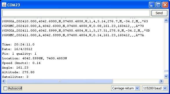
In this sketch, we call GPS.read() within a once-a-millisecond timer (this is the same timer that runs the millis() command). Then in the main loop we can ask if a new chunk of data has been received by calling GPS.newNMEAreceived(), if this returns true then we can ask the library to parse that data with GPS.parse(GPS.lastNMEA()).
We do have to keep querying and parsing in the main loop - its not possible to do this in an interrupt because then we'd be dropping GPS data by accident.
Once data is parsed, we can just ask for data from the library like GPS.day, GPS.month and GPS.year for the current date. GPS.fix will be 1 if there is a fix, 0 if there is none. If we have a fix then we can ask for GPS.latitude, GPS.longitude, GPS.speed (in knots, not mph or k/hr!), GPS.angle, GPS.altitude (in centimeters) and GPS.satellites (number of satellites)
This should make it much easier to have location-based projects. We suggest keeping the update rate at 1Hz and request that the GPS only output RMC and GGA as the parser does not keep track of other data anyways.
Battery Backup
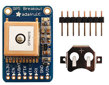
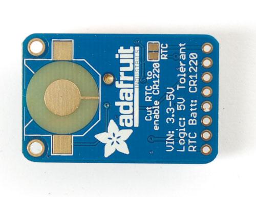
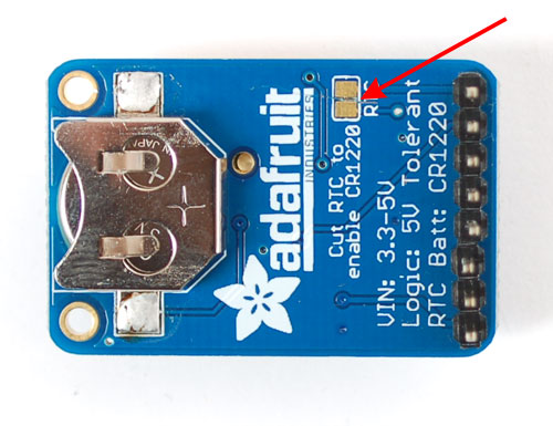
The GPS has a built in real time clock, which can keep track of time even when it power is lost and it doesn't have a fix yet. It can also help reduce fix times, if you expect to have a flakey power connection (say you're using solar or similar). To use the RTC, we need to attach a battery. There is a spot on the back for a CR1220 sized battery holder. We provide the holder but the battery is not included. You can use any 12mm coin cell - these are popular and we also carry them in the Adafruit shop.
Before inserting a battery into the battery holder, first cut the trace between the two solder pads on the back, labeled RTC (this disconnects the VIN pin from the battery input) Use a multimeter with continuity checking to verify the two pads are no longer tied together.
Advanced Wiring
Thus far we've only used the VIN GND TX and RX pins of the GPS - but there are many other pins. What do these do and will you ever need them? Chances are, for 90% of GPS projects, the other pins are not required. But we do make them available in case you have a specific need.
FIX is an output pin - it is the same pin as the one that drives the red LED. When there is no fix, the FIX pin is going to pulse up and down once every second. When there is a fix, the pin is low (0V) for most of the time, once every 15 seconds it will pulse high for 200 milliseconds
VBAT is an input pin - it is connected to the GPS real time clock battery backup. We suggest using the battery spot on the back but if you have a project with a coin cell or other kind of battery that you want to use (and its under 3.3V) you can connect it to the VBAT pin. If you do this, be sure to cut the trace on the back between the RTC solder pads
EN is the Enable pin, it is pulled high with a 10K resistor. When this pin is pulled to ground, it will turn off the GPS module. This can be handy for very low power projects where you want to easily turn the module off for long periods. You will lose your fix if you disable the GPS so keep that in mind.
3.3V is the output from the onboard 3.3V regulator. If you have a need for a clean 3.3V output, you can use this! It can provide at least 100mA output.
Built in Logging
One of the nice things about the MTK3339 is the built in data-logger. This basic data-logging capability can store date, time, latitude, longitude and altitude data into a 64K flash chip inside. Its not a high resolution logger - it only logs once every 15 seconds when there is a fix - but for 99% of projects that want to track location, this can be a great low power way to log data - no SD card or other EEPROM required! It can store up to 16 hours of data.
The GPS module does require a microcontroller to 'kick start' the logger by requesting it to start. If power is lost it will require another 'kick' to start. If you already have some data in the FLASH, a new trace will be created (so you wont lose old data) and if you run out of space it will simply halt and not overwrite old data. Despite this annoyance, its still a very nice extra and we have some library support to help you use it
First, we should try getting the logger to run.Open up the File→Examples→Adafruit_GPS→locus_start sketch. This will demonstrate how to start the logger (called LOCUS)
|
|
{{{text}}} |
Source
- AdaFruit notre fournisseur.
Outils
- Ensemble des commandes MTK3329/MTK3339 permettant de changer la fréquence de mise-à-jour, le débit (bauds), la syntaxe de sortie, etc!
- Fiche technique du PA6B (MTK3329), module GPS
- Fiche technique du PA6C (MTK3339), module GPS
- MT3339 GPS PC Tool (windows uniquement) et son manuel
- Mini GPS tool (windows uniquement)
Où Acheter
Le module GPS Ultimate d'AdaFruit est disponible chez MC Hobby.
Traduit avec l'autorisation d'AdaFruit Industries - Translated with the permission from Adafruit Industries - www.adafruit.com
Toute référence, mention ou extrait de cette traduction doit être explicitement accompagné du texte suivant : « Traduction par MCHobby (www.MCHobby.be) - Vente de kit et composants » avec un lien vers la source (donc cette page) et ce quelque soit le média utilisé.
L'utilisation commercial de la traduction (texte) et/ou réalisation, même partielle, pourrait être soumis à redevance. Dans tous les cas de figures, vous devez également obtenir l'accord du(des) détenteur initial des droits. Celui de MC Hobby s'arrêtant au travail de traduction proprement dit.
