Différences entre versions de « DRV8825 »
| Ligne 114 : | Ligne 114 : | ||
{{ambox-stop|text=This product can get hot enough to burn you long before the chip overheats. Take care when handling this product and other components connected to it.}} | {{ambox-stop|text=This product can get hot enough to burn you long before the chip overheats. Take care when handling this product and other components connected to it.}} | ||
| − | {{underline|Please note that measuring the current draw at the power supply will generally not provide an accurate measure of the coil current.}} Since the input voltage to the driver can be significantly higher than the coil voltage, the measured current on the power supply can be quite a bit lower than the coil current (the driver and coil basically act like a switching step-down power supply). Also, if the supply voltage is very high compared to what the motor needs to achieve the set current, the duty cycle will be very low, which also leads to significant differences between average and RMS currents. Additionally, please note that the coil current is a function of the set current limit, but it does not necessarily equal the current limit setting. The actual current through each coil changes with each microstep. See the DRV8825 datasheet for more information. | + | {{underline|Please note that measuring the current draw at the power supply will generally not provide an accurate measure of the coil current.}} Since the input voltage to the driver can be significantly higher than the coil voltage, the measured current on the power supply can be quite a bit lower than the coil current (the driver and coil basically act like a switching step-down power supply). Also, if the supply voltage is very high compared to what the motor needs to achieve the set current, the duty cycle will be very low, which also leads to significant differences between average and RMS currents. Additionally, please note that the coil current is a function of the set current limit, but it does not necessarily equal the current limit setting. The actual current through each coil changes with each microstep. See the DRV8825 datasheet for more information. |
== Diagramme == | == Diagramme == | ||
Version du 29 juin 2014 à 19:04
Présentation
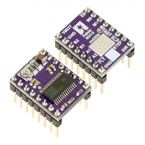
Ce breakout de contrôle moteur pas-à-pas DRV8825 est basé sur le DRV8825 de Texas Instrument pouvant piloter un moteur pas-à-pas en micro-stepping (micro pas). Le module dispose d'un brochage et interface presque identique à notre contrôleur de moteur pas-à-pas A4988. Il peut donc être directement utiliser en replacement sur les différentes cartes d'interface avec ce modèle haute performance.
Le DRV8825 intègre un limiteur de courant actif et réglable. Vous disposez également d'une protection contre les surcourant, la surchauffe avec 6 résolutions de micro-stepping (jusqu'au 1/32 de pas). Il fonctionne entre 8.2 et 45 V et sais délivrer apprimativement 1.5 A par phase sans refroidissement (par refroidisseur ou air forcé - conçu pour 2.2A par bobine en utilisant un système de refroidissement efficace/adéquat).
Nous recommandons de lire attentivement la fiche technique du DRV8825 (1Mb pdf) et notre tutoriel avant d'utiliser le produit. Ce pilote est capable de contrôler un moteur pas-à-pas bipolaire avec un courant allant jusqu'a 2.2 Amp par bobine (voyez la section dévolue à la Dissipation de Chaleur pour plus d'information).
Détails techniques
Voici quelque-unes des caractéristiques clés:
- Interface de contrôle super-simple pour les pas et de la direction.
- 6 résolutions de pas: Pas complet (full-step), demi-pas, 1/4 de pas, 1/8 de pas, 1/16 de pas et 1/32 de pas
- Contrôle du courant ajustable vous permettant de fixer le courant maximum pouvant passer dans les bobine. Le réglage se fait à l'aide d'un potentiomètre. Vous pouvez donc utiliser votre moteur pas-à-pas avec une tension plus élevée... vous permettant ainsi d'atteindre des vitesses plus élevées.
- Electronique de contrôle de "coupure" intelligent sélectionnant automatiquement le mode de décroissance du courant (décroissance rapide ou lente)
- Intelligent chopping control that automatically selects the correct current decay mode
- Tension d'alimentation max: 45 V
- Régulateur de tension intégré (donc pas besoin d'une tension externe pour alimenter la logique de contrôle).
- Peut s'interfacer directement avec des systèmes 3.3 V et 5 V
- Coupure automatique en cas de surchauffe. Coupure en cas de surcourant.
- Blocage en sous-tension (pour éviter les fonctionnements erratiques/imprévisibles de l'électronique de commande)
- Protection de retour à la masse (short-to-ground) et de court-circuit de la charge (shorted-load).
- Carte 4 couches utilisant plus de cuivre pour améliorer la dissipation de chaleur.
- Pastille de masse soudable exposé sous le circuit intégré (sur la surface inférieure de la carte)
- La taille du module, le brochage et l'interface correspond au StepStick A4988 sous de nombreux aspects (voyez le tutoriel pour plus d'information)
- Fiche technique du DRV8825
Brochage
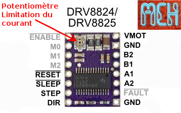
- Enable: Logique Inversée, permet d'activer ou désactivé le moteur. Etat Haut=High=Moteur actif... et axe bloqué entre les pas. Etat bas=Low=Axe totalement libre
- M0, M1, M2: permet de sélectionner la configuration Step/MicroStep. Ces broches disposent de résistances Pull-Down ramenant le potentiel à 0v lorsque rien n'est connecté sur ces broches. Voir la section ci-dessous pour plus d'information.
- Reset: Logique inversée. Permet de faire une réinitialisation du module. Généralement connecté sur la broche "sleep", voir le schéma ci-dessous.
- Sleep: Logique inversée. Généralement connecté sur la broche "Reset" du module.
- Step: Envoyer un signal d'horloge (Niveau Haut puis Niveau bas, High puis Low) pour avancer le moteur d'un pas.
- DIR: Permet d'indiquer la direction de rotation du moteur. Etat Haut=High pour tourner dans un sens, Etat bas=Low pour tourner dans l'autre sens.
- VMot: Tension d'alimentation pour les moteurs pas à pas. Tension entre 8.2 et 45v.
- GND: Sous "VMOT", masse pour l'alimentation moteur.
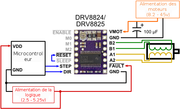
- A1 A2: Première bobine du moteur pas à pas bipolaire (voir exemple ci-dessous)
- B1 B2: Deuxième bobine du moteur pas à pas bipolaire (voir exemple ci-dessous)
Alimentation de la logique de contrôle:
- Fault: Logique inversée. Branchez une tension entre 2.5 et 5.25v, celle qui alimente votre microcontrôleur.
- GND: sous FAULT. Masse commune avec votre microcontrôleur.
Connecter l'Alimentation
The driver requires a motor supply voltage of 8.2 – 45 V to be connected across VMOT and GND. This supply should have appropriate decoupling capacitors close to the board, and it should be capable of delivering the expected stepper motor current.
| Warning: This carrier board uses low-ESR ceramic capacitors, which makes it susceptible to destructive LC voltage spikes, especially when using power leads longer than a few inches. Under the right conditions, these spikes can exceed the 45 V maximum voltage rating for the DRV8825 and permanently damage the board, even when the motor supply voltage is as low as 12 V. One way to protect the driver from such spikes is to put a large (at least 47 µF) electrolytic capacitor across motor power (VMOT) and ground somewhere close to the board. |
Connecter le moteur
Four, six, and eight-wire stepper motors can be driven by the DRV8825 if they are properly connected; a FAQ answer explains the proper wirings in detail.
| Connecting or disconnecting a stepper motor while the driver is powered can destroy the driver. (More generally, rewiring anything while it is powered is asking for trouble.) |
Step et micro-Stepping
Stepper motors typically have a step size specification (e.g. 1.8° or 200 steps per revolution), which applies to full steps. A microstepping driver such as the DRV8825 allows higher resolutions by allowing intermediate step locations, which are achieved by energizing the coils with intermediate current levels. For instance, driving a motor in quarter-step mode will give the 200-step-per-revolution motor 800 microsteps per revolution by using four different current levels.
The resolution (step size) selector inputs (MODE0, MODE1, and MODE2) enable selection from the six step resolutions according to the table below. All three selector inputs have internal 100kΩ pull-down resistors, so leaving these three microstep selection pins disconnected results in full-step mode. For the microstep modes to function correctly, the current limit must be set low enough (see below) so that current limiting gets engaged. Otherwise, the intermediate current levels will not be correctly maintained, and the motor will skip microsteps.
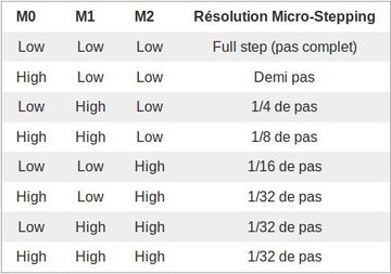
High est un signal haut (entre 2.5 et 5.25v) et Low un signal bas (0v)
Contrôle des entrées
Each pulse to the STEP input corresponds to one microstep of the stepper motor in the direction selected by the DIR pin. These inputs are both pulled low by default through internal 100kΩ pull-down resistors. If you just want rotation in a single direction, you can leave DIR disconnected.
The chip has three different inputs for controlling its power states: RESET, SLEEP, and ENBL. For details about these power states, see the datasheet. Please note that the driver pulls the SLEEP pin low through an internal 1MΩ pull-down resistor, and it pulls the RESET and ENBL pins low through internal 100kΩ pull-down resistors. These default RESET and SLEEP states are ones that prevent the driver from operating; both of these pins must be high to enable the driver (they can be connected directly to a logic “high” voltage between 2.2 and 5.25 V, or they can be dynamically controlled via connections to digital outputs of an MCU). The default state of the ENBL pin is to enable the driver, so this pin can be left disconnected.

Schematic of nSLEEP and nFAULT pins on DRV8824/DRV8825/DRV8834 carriers.
The DRV8825 also features a FAULT output that drives low whenever the H-bridge FETs are disabled as the result of over-current protection or thermal shutdown. The carrier board connects this pin to the SLEEP pin through a 10k resistor that acts as a FAULT pull-up whenever SLEEP is externally held high, so no external pull-up is necessary on the FAULT pin. Note that the carrier includes a 1.5k protection resistor in series with the FAULT pin that makes it is safe to connect this pin directly to a logic voltage supply, as might happen if you use this board in a system designed for the pin-compatible A4988 carrier. In such a system, the 10k resistor between SLEEP and FAULT would then act as a pull-up for SLEEP, making the DRV8825 carrier more of a direct replacement for the A4988 in such systems (the A4988 has an internal pull-up on its SLEEP pin). To keep faults from pulling down the SLEEP pin, any external pull-up resistor you add to the SLEEP pin input should not exceed 4.7k.
Limitation de courant
Le contrôle actif du courant - Un avantage clé
Ce pilote de moteur pas-à-pas dispose d'un circuit actif de limitation de courant. C'est une caractéristique assez incroyable car elle permet de piloter des moteurs pas-à-pas avec une tension plus élevée sans griller le moteur. Admettons que vous avez un moteur prévu pour 2.8V à 1.7 ampère. S'il alimenté directement avec une tension de 5.6 Volts (le double à titre d'exemple) alors la bobine laisserait alors passer un courant de 3.4 Amp. Cependant, à 3.4 Amp, la bobine chauffe tellement que le moteur grille rapidement (l'échauffement augmente au carré du courant!).
Mais si vous disposez d'un circuit limitant activement le courant, vous pourriez régler celui-ci sur 1.7A max (ou 1.5A, le maximum du DRV8825). Par conséquent, même si vous alimentez le moteur en 5.6v, le courant ne pourra pas dépasser 1.7 Amp (1.5A pour le DRV8825) et le moteur ne grille pas.
Quel sont les avantages à utiliser une tension plus élevée?
- Le moteur est plus beaucoup plus réactif.
- Le passage d'un pas à l'autre plus rapide avec un tension plus élevée car le champ magnétique est plus puissant.
- Si le moteur est plus réactif alors vous pouvez également atteindre des vitesses plus élevées.
- Avec une tension plus élevée, vous pouvez utiliser un piloter nécessitant une tension minimale de fonctionnement plus importante (comme le DRV8825) même avec un moteur en assez basse tension. Du moment que le courant est limité activement, il n'y aura pas de dégât sur les bobines.
Concernant le moteur 2.8V 1.7Amp mentionné, vous pourriez le piloter avec une alimentation 9V (confirmé par Pololu) avec un DRV8825 en limitant activement le courant à 1.5Amp (le maximum toléré par le DRV8825 sans refroissement).
Réglage - comment faire
To achieve high step rates, the motor supply is typically much higher than would be permissible without active current limiting. For instance, a typical stepper motor might have a maximum current rating of 1 A with a 5Ω coil resistance, which would indicate a maximum motor supply of 5 V. Using such a motor with 12 V would allow higher step rates, but the current must actively be limited to under 1 A to prevent damage to the motor.
The DRV8825 supports such active current limiting, and the trimmer potentiometer on the board can be used to set the current limit. You will typically want to set the driver’s current limit to be at or below the current rating of your stepper motor. One way to set the current limit is to put the driver into full-step mode and to measure the current running through a single motor coil without clocking the STEP input. The measured current will be 0.7 times the current limit (since both coils are always on and limited to approximately 70% of the current limit setting in full-step mode).
Another way to set the current limit is to measure the voltage on the “ref” pin and to calculate the resulting current limit (the current sense resistors are 0.100Ω). The ref pin voltage is accessible on a via that is circled on the bottom silkscreen of the circuit board. The current limit relates to the reference voltage as follows:
Current Limit = VREF × 2
So, for example, if you have a stepper motor rated for 1 A, you can set the current limit to 1 A by setting the reference voltage to 0.5 V.
| Note: The coil current can be very different from the power supply current, so you should not use the current measured at the power supply to set the current limit. The appropriate place to put your current meter is in series with one of your stepper motor coils. |
Dissipation de chaleur - considérations
The DRV8825 driver IC has a maximum current rating of 2.5 A per coil, but the current sense resistors further limit the maximum current to 2.2 A, and the actual current you can deliver depends on how well you can keep the IC cool. The carrier’s printed circuit board is designed to draw heat out of the IC, but to supply more than approximately 1.5 A per coil, a heat sink or other cooling method is required.
| This product can get hot enough to burn you long before the chip overheats. Take care when handling this product and other components connected to it. |
Please note that measuring the current draw at the power supply will generally not provide an accurate measure of the coil current. Since the input voltage to the driver can be significantly higher than the coil voltage, the measured current on the power supply can be quite a bit lower than the coil current (the driver and coil basically act like a switching step-down power supply). Also, if the supply voltage is very high compared to what the motor needs to achieve the set current, the duty cycle will be very low, which also leads to significant differences between average and RMS currents. Additionally, please note that the coil current is a function of the set current limit, but it does not necessarily equal the current limit setting. The actual current through each coil changes with each microstep. See the DRV8825 datasheet for more information.
Diagramme
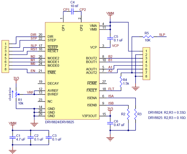
The current sense resistors (R2 and R3) on the DRV8825 carrier are 0.100 Ω. This schematic is also available as a downloadable pdf (196k pdf).
DRV8825 et A4988 - les différences clés
xx
Où Acheter
Vous trouverez également les produits suivants:
A voir aussi
Documentation réalisée par Meurisse. D pour MCHobby.be. En partie basé sur les informations disponible sur le site de Pololu
Traduit avec l'autorisation de Pololu - Translated with the permission from Pololu - www.pololu.com
Toute référence, mention ou extrait de cette traduction doit être explicitement accompagné du texte suivant : « Traduction par MCHobby (www.MCHobby.be) - Vente de kit et composants » avec un lien vers la source (donc cette page) et ce quelque soit le média utilisé.
L'utilisation commercial de la traduction (texte) et/ou réalisation, même partielle, pourrait être soumis à redevance. Dans tous les cas de figures, vous devez également obtenir l'accord du(des) détenteur initial des droits. Celui de MC Hobby s'arrêtant au travail de traduction proprement dit.
Traduit avec l'autorisation d'AdaFruit Industries - Translated with the permission from Adafruit Industries - www.adafruit.com
