Différences entre versions de « Modèle:EZ-LINK-TOUR »
| Ligne 16 : | Ligne 16 : | ||
The two blue LEDs are for monitoring the data received & sent. When data is sent from the computer to the module, the '''TX''' LED will blink. When data is sent from the module to the paired computer, the '''RX''' LED will blink. You can use this to debug your wiring and connection. | The two blue LEDs are for monitoring the data received & sent. When data is sent from the computer to the module, the '''TX''' LED will blink. When data is sent from the module to the paired computer, the '''RX''' LED will blink. You can use this to debug your wiring and connection. | ||
| − | == Bouton "PAIR" == | + | == Bouton "PAIR" (appairage) == |
The pair button is used to reset the computer pairing for Bluetooth link. If you want to re-pair the module, press the button for 5 seconds, you'll see the red LED fast-blink to indicate its ready for pairing! You can now use your computer to Bluetooth-scan for the EZ-Link device. | The pair button is used to reset the computer pairing for Bluetooth link. If you want to re-pair the module, press the button for 5 seconds, you'll see the red LED fast-blink to indicate its ready for pairing! You can now use your computer to Bluetooth-scan for the EZ-Link device. | ||
Version du 19 juin 2014 à 10:37
Intro
Bluefruit EZ-Link is the ultimate bluetooth module! Lets take a tour of all the great stuff we packed onto this device.

Crédit: AdaFruit Industries www.adafruit.com
Module RF
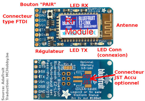
In the center is the bluetooth radio module. This module does all the heavy lifting of creating the RF connection and sending data back and forth. It's a custom module made for Adafruit and is FCC and CE certified.
LEDs
There are three LEDs, one red and two blue.
The red Connection LED is used to indicate the state of the bluetooth connection/link. If it is slow-blinking, there is no pairing for the module. If it is fast blinking, it's paired to a computer and the wireless connection is 'live' - the computer has opened a UART connection and is sending/receiving data.
The two blue LEDs are for monitoring the data received & sent. When data is sent from the computer to the module, the TX LED will blink. When data is sent from the module to the paired computer, the RX LED will blink. You can use this to debug your wiring and connection.
Bouton "PAIR" (appairage)
The pair button is used to reset the computer pairing for Bluetooth link. If you want to re-pair the module, press the button for 5 seconds, you'll see the red LED fast-blink to indicate its ready for pairing! You can now use your computer to Bluetooth-scan for the EZ-Link device.
Level Shifter et Regulateur de tension
There is an on-board regulator that can take 3-16VDC and convert it to 3V to power the RF module. The regulator is also reverse-polarity protected. Onboard level-shifting circuitry converts any input data signal to be 3V safe, so you can use a 5V microcontroller.
Signaux d'entrée/sortie
Connecteur type FTDI.
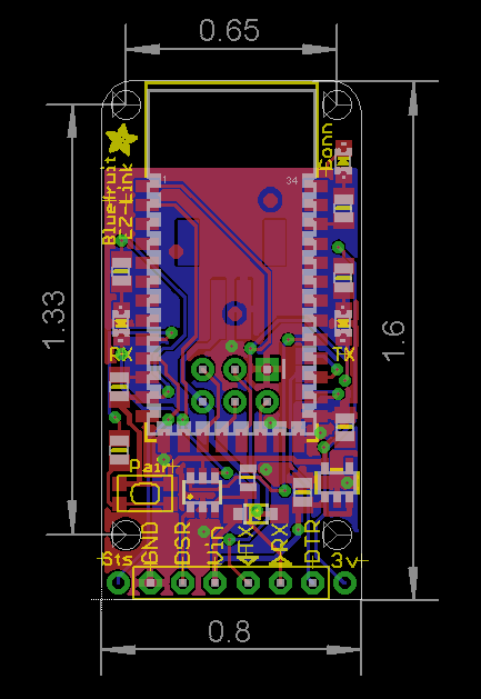
The row of 8 0.1" spaced holes at the bottom are used for signal rx/tx and power. Pour plus de détails, voyez la page consacrée au brochage.
Connecteur d'accu JST
On the back is an optional JST connection that can be soldered with a JST PH-2 socket for powering the module with a battery such as one of accus Lithium Polymère. When a battery is plugged in, the Vin breakout pin will act as a power output and can be used to power your microcontroller.
Trous de montage
Quatre trous de 2mm permettent d'attacher l'EZ-Link, voyez ci-dessous!

Crédit: AdaFruit Industries www.adafruit.com