Pont-H L298N
Introduction
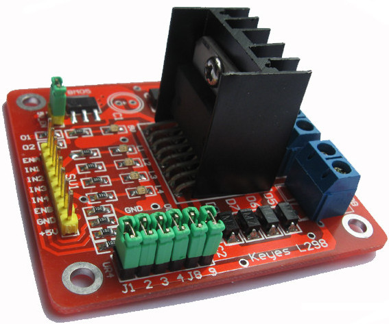
Ce breakout board est un Double Pont-H destiné au contrôle de moteur continu (H-Bridge Motor Driver). Il est basé sur le composant L298N qui est un double Pont-H conçu spécifiquement pour ce cas d'utilisation.
C'est un module extrêmement utile pour le contrôler de robots et ensembles mécanisés. Il peut contrôler deux moteur courant continu ou un moteur pas-à-pas 4 fils 2 phases. il est conçu pour supporter des tensions plus élevées, des courants importants tout en proposant une commande logique TTL (basse tenstion, courant faibles, idéal donc pour un microcontrôleur).
Il peut piloter des charges inductives comme des relais, solénoides, moteurs continus et moteurs pas-à-pas. Les deux types de moteurs peuvent être contrôlés aussi bien en vitesse (PWM) qu'en direction. Toutes les sorties en puissance sont déjà protégées par des diodes anti-retour.
Il s'agit d'un module prêt à l'emploi.
Caractéristiques
- Léger, petit
- Des capacités hors-pair pour contrôle moteur
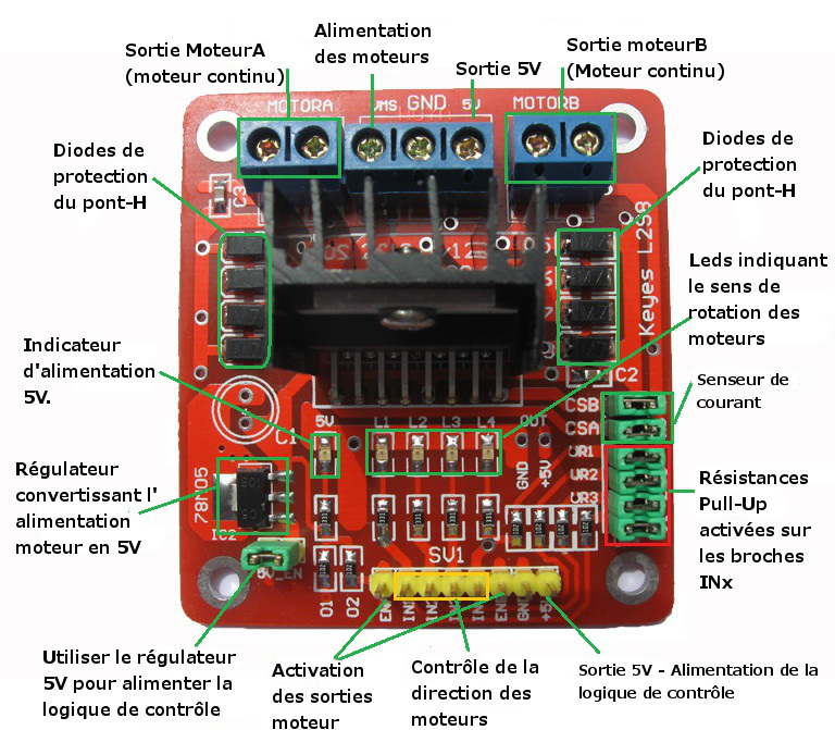
- Diodes de protections
- Un dissipateur (pour dissiper la chaleur en cas de forte charge)
- Un sélecteur pour sélectionner la source d'alimentationPower selection switch
- 4 Sélecteurs pour les résistances pull up
- Sortie pour 2 moteurs continu/ 1 moteur pas-à-pas (4 bobines, deux phases)
- Indicateur LED pour sens de rotation moteur
- Indicateur LED pour alimentation 5V
- 4 trous de fixation standard
Spécifications
- Composant de contrôle en puissance: L298N
- Alimentation de la charge: de +6V à +35V
- Courant Max (en pointe): 2A
- Tension de commande logique Vss: de +5 à +7V (alimentation interne de +5V)
- Courant de commande logique: de 0 à 36mA
- Tensions pour contrôle du sens: Low -0.3V~1.5V, high: 2.3V~Vss
- Tensions pour contrôle "Enable": Low -0.3V~1.5V, high: 2.3V~Vss
- Puissance Max: 25W (Température 75 ℃)
- Température de fonctionnement: de -25℃ à +130℃
- Dimensions: 60mm x 54mm
- Poids: ~48g
Application Ideas
- drive brushed DC motors
- drive 4-wire two-phase stepper motor
Cautions
- Ensure that the positive and negative pole connected to the VMS and GND
- Input voltage not exceeding 35V
Hardware Diagram
| Port name | Direction | Description | Usage |
| VMS GND | / | connect to external power supply(6V~35V) | ENA(ENB) connected to H state will enable MOTORA(MOTORB) IN1(IN3) connected to 5V and IN2(IN4) to GND MOTORA(MOTORB) will move clockwise IN1(IN3) connected to GND and IN2(IN4) to 5V MOTORA(MOTORB) will move Anti-clockwise if you cwant to control speed you can connect the ENA(ENB) to PWM. |
| ENA | Input | TTL Compatible Enable Input:the L state disables the bridge A | |
| IN1 | Input | TTL Compatible Inputs of the Bridge A | |
| IN2 | Input | TTL Compatible Inputs of the Bridge A | |
| ENB | Input | TTL Compatible Enable Input:the L state disables the bridge B | |
| IN3 | Input | TTL Compatible Inputs of the Bridge B | |
| IN4 | Input | TTL Compatible Inputs of the Bridge B | |
| M)TORA | Output | Output of the Bridge A | |
| MOTORB | Output | Output of the Bridge B | |
| CSA(CSB) | / | use for testing electric current of Bridge A(Bridge B) | |
| UR1 UR2 UR3 UR4 | / | pull-up resistor | |
| 5V +5V | / | 5V output | |
| 5V Chip Enable Jumper | / | if connected,5V chip will work. |
Getting Started
How to use Jumpers
- 5V-Enable jumper:
When you connect the 5V-Enable,the 78M05 will output 5V to supply logic chip,if you take off,you must connect 5V to supply logic chip.
- Pull up resistor jumpers
Only if you connect IN1(IN2 IN3 IN4) to MCU which have ports of strong driving ability such as AVR,you can take off the jumpers.
How to connected to your control board
DC motor input port A has three pins,IN1,IN2 and ENA.IN1 and IN2 are digital ports which are used to control the direction of motor,ENA is usually connected to PWM port of control board to control the speed of motor,also it can be connected to digital port. we can control the 4-wire stepping motor the same way as two DC motors with the signal form ENA,IN1,IN2 and ENB,IN3,IN4.
Examples
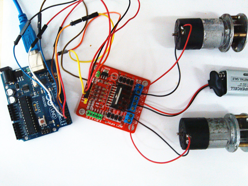
Drive Two DC Motors
To do this Demo required:
- Hardware: two DC motors, one Arduino, one L298 Shield,external power supply.
- Software: Arduino IDE,program.
Connect Arduino and L298 shield according to program notes,then upload the sketch to the Arduino board.
int ENA=5;//connected to Arduino's port 5(output pwm)
int IN1=2;//connected to Arduino's port 2
int IN2=3;//connected to Arduino's port 3
int ENB=6;//connected to Arduino's port 6(output pwm)
int IN3=4;//connected to Arduino's port 4
int IN4=7;//connected to Arduino's port 7
void setup()
{
 pinMode(ENA,OUTPUT);//output
 pinMode(ENB,OUTPUT);
 pinMode(IN1,OUTPUT);
 pinMode(IN2,OUTPUT);
 pinMode(IN3,OUTPUT);
 pinMode(IN4,OUTPUT);
 digitalWrite(ENA,LOW);
 digitalWrite(ENB,LOW);//stop driving
 digitalWrite(IN1,LOW);
 digitalWrite(IN2,HIGH);//setting motorA's directon
 digitalWrite(IN3,HIGH);
 digitalWrite(IN4,LOW);//setting motorB's directon
}
void loop()
{
  analogWrite(ENA,255);//start driving motorA
  analogWrite(ENB,255);//start driving motorB

}
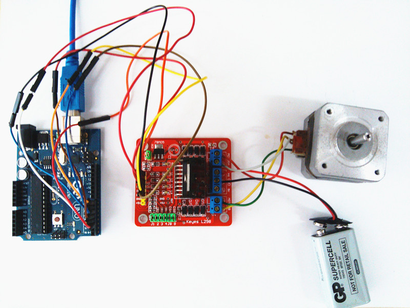
Drive Two phase 4-wire stepping motor
To do this Demo required:
- Hardware: one 4-wires stepping motors, one Arduino, one L298 Shield,external power supply.
- Software: Arduino IDE,program.
Firstly,we should use the multimeter to detect the 4 wires,the 2 wires which connected is a group.In this example,the red wire and gray wires are a group(call A group),the yellow wire and green wire are a group(call B group).Connect Arduino and L298 shield according to the picture above and program notes,then upload the sketch to the Arduino board.
int ENA=2;//connected to Arduino's port 2
int IN1=3;//connected to Arduino's port 3
int IN2=4;//connected to Arduino's port 4
int ENB=5;//connected to Arduino's port 5
int IN3=6;//connected to Arduino's port 6
int IN4=7;//connected to Arduino's port 7

void setup()
{
 pinMode(ENA,OUTPUT);
 pinMode(ENB,OUTPUT);
 pinMode(IN1,OUTPUT);
 pinMode(IN2,OUTPUT);
 pinMode(IN3,OUTPUT);
 pinMode(IN4,OUTPUT);
 digitalWrite(ENA,HIGH);//enablae motorA
 digitalWrite(ENB,HIGH);//enable motorB
}
void loop()
{/*In the way of 4 beats to drive the stepping motor,A group connected to motorA,B
 B group connected to motorB,Suppose A representing the forward current of A group,
 A- representing the reverse current of A group,B representing the forward current of B group,
 B- representing the reverse current of B group.
 this way run as follow:
 AB    A-B    A-B-   AB-
 or
 AB   AB-    A-B-   A-B
 */
 digitalWrite(IN1,LOW);
 digitalWrite(IN2,HIGH);
 digitalWrite(IN3,HIGH);
 digitalWrite(IN4,LOW);
 delay(10);
 digitalWrite(IN1,LOW);
 digitalWrite(IN2,HIGH);
 digitalWrite(IN3,LOW);
 digitalWrite(IN4,HIGH);
 delay(10);
 digitalWrite(IN1,HIGH);
 digitalWrite(IN2,LOW);
 digitalWrite(IN3,LOW);
 digitalWrite(IN4,HIGH);
 delay(10);
 digitalWrite(IN1,HIGH);
 digitalWrite(IN2,LOW);
 digitalWrite(IN3,HIGH);
 digitalWrite(IN4,LOW);
 delay(10);
}
Resources
How to buy
Dual H-Bridge Motor Driver can be ordered through the GOF store. Its product page is located here
Licence GeekOnFire
Cette document est fournie sous la licence Creative Commons Attribution-ShareAlike License 3.0. Le code source et les librairies sont sous licence GPL/LGPL, voir le code source des fichiers pour plus d'information.
Note de traduction
Le contenu de cette page est une traduction "At the best" des informations mise à disposition par Geek On Fire (page originale).
En aucun cas, MC Hobby ne peut être tenu responsable de l'exactitude des informations fournie par Geek On Fire ainsi que des conséquences qui pourraient en découler.
Cette traduction est proposée gratuitement comme aide ponctuelle visant à accélérer la prise en main. Une erreur de traduction n'engage, en aucun cas, la responsabilité de MC Hobby.
En cas de doute, l'utilisateur peut se référer au document d'origine mis à disposition par Geek On Fire.
Traduit avec l'autorisation de Geek On Fire - Translated with the permission from Geek On Fire - [1] Toute référence, mention ou extrait de cette traduction doit être explicitement accompagné du texte suivant : « Traduction par MCHobby (www.MCHobby.be) - Vente de kit et composants » avec un lien vers la source (donc cette page) et ce quelque soit le média utilisé.
L'utilisation commercial de la traduction (texte) et/ou réalisation, même partielle, pourrait être soumis à redevance. Dans tous les cas de figures, vous devez également obtenir l'accord du(des) détenteur initial des droits. Celui de MC Hobby s'arrêtant au travail de traduction proprement dit.


