AdaFruit Proto Shield Souder
Il est temps de souder les éléments du kit!
Si vous n'avez jamais souder avant ce jour, jetez un oeil sur les préparatifs pour tutoriels.
Etape 0: Contrôle
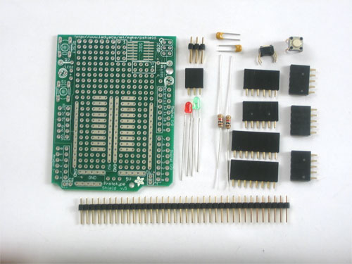
La première chose à faire est de vérifier la liste des composants. Vérifiez la liste des composants à l'aide du lien "Liste des pièces" disponible en haut à droite de cette page. Note: Le PinHeader à 3 broches n'est plus inclus depuis que nous utilisons seulement les Arduino NG (dernière révision USB)!
Etape 1: les boutons
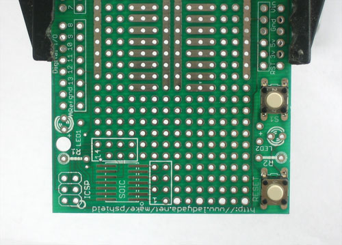
Placer les deux boutons. Ils devraient parfaitement se positionner sur leur emplacement et traverser la carte (le PCB). Pas besoin de vous inquiéter de mal les monter car les boutons sont symétriques.
Etape 2: sourdure
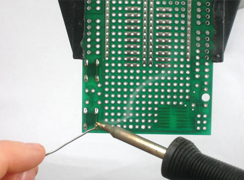
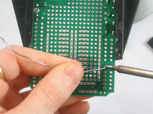
Souder les 4 points des boutons à l'aide de votre fer à souder.
Etape 3
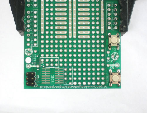
Ensuite, placez le PinHeader ICSP à 6 broches. Vous pouvez sauter cette étape si vous êtes décidé à ne jamais utiliser de programmateur externe!
Etape 4
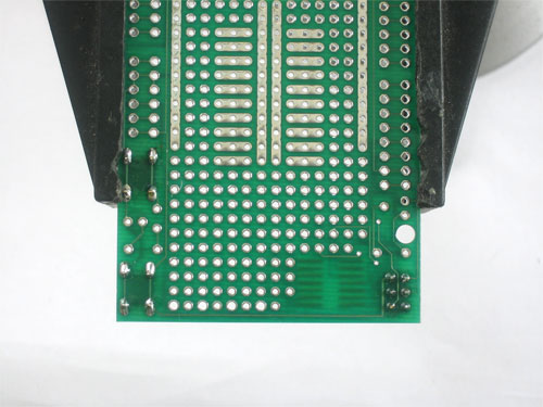
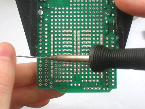
Solder all 6 pins. You may have to tape or hold the part in place or it'll fall out!
Etape 5
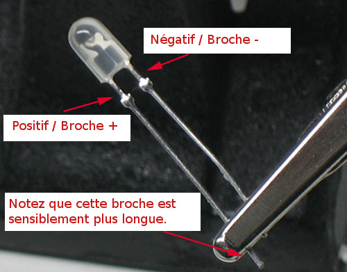
Next its time to place the two 3mm LEDs. LEDs are directional, and if you put them in backwards they wont work.
LEDs have a positive lead and a negative lead. The positive lead is longer.
Etape 6
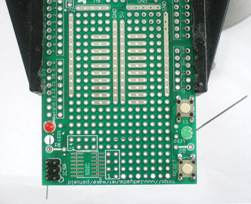
On the Protoshield PCB you will see a small + sign next to the LED silkscreen pictures. That's the side you should put the positive lead in.
Etape 7
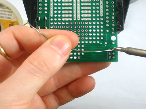
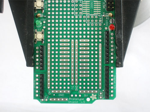
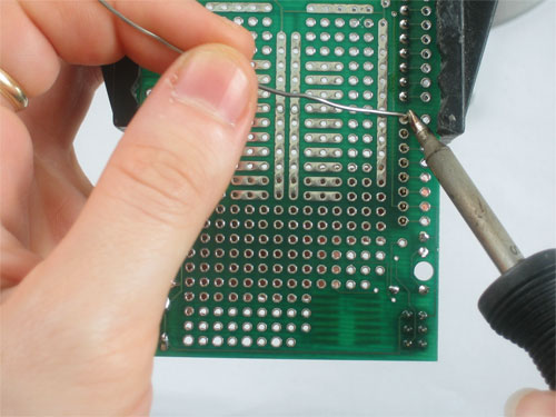
Souder les deux LEDs dans leur emplacement. Celle qui est visible sur cette image mais également celle située au gauche de la carte (juste visible au dessus de la main)
Etape 8
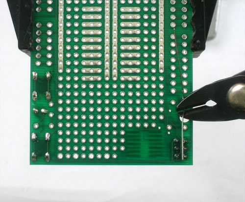
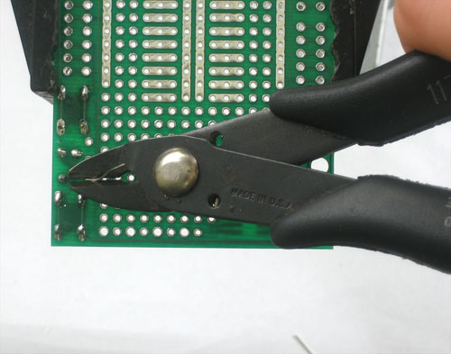
Use diagonal cutters to snip off the long legs so that they are about as long as the legs of the buttons or ICSP header
Etape 9
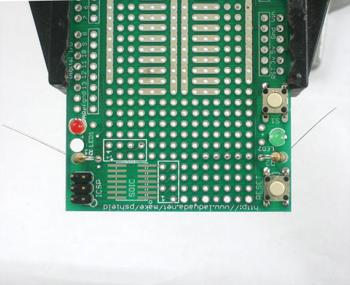
Next place the two resistors for the LEDs. Resistors don't have a direction so you can put them in either way.
Etape 10
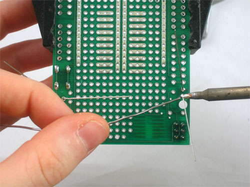
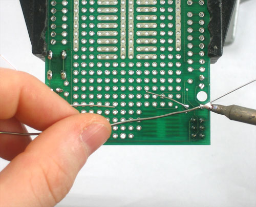
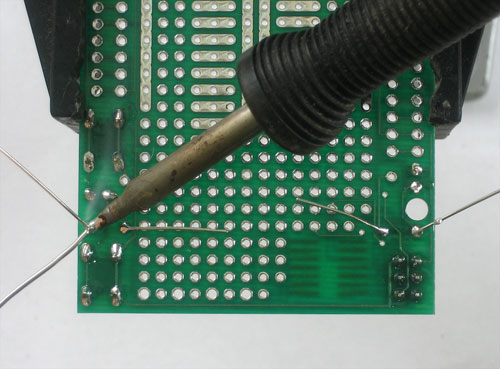
Solder in the resistor legs and clip them short.
Etape 11
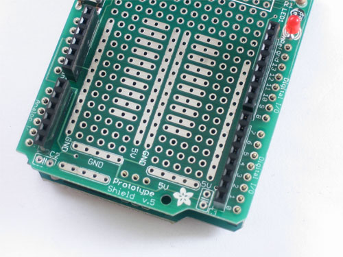
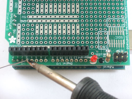
Next, place the 4 8-pin and 6-pin female headers as shown.
Etape 12
Turn the board over and solder them in, you may have to hold the parts or tape them to keep them from falling out!
Etape 13
devrait etre vide, renommer les autres points --1 Fichier:ADF-ProtoShield-Souder13.jpg
Etape 14
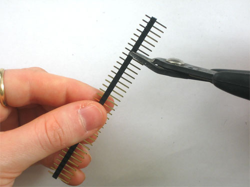
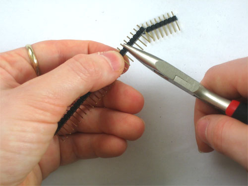
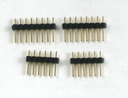
Next its time to make the male headers from the long strip. use diagonal cutters or pliers to clip off 4 parts, 2 6-pin and 2 8-pin, as shown.
Etape 15
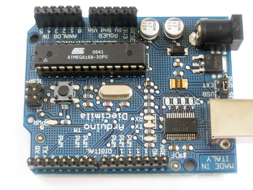
If you have a Diecimila (2008), Duemilanove (2009) or newer Arduino, put the long ends of the male header in to the female header on the Arduino, as shown
Etape 16
Put the proto shield on top of the Arduino, so that the male header aligns with the solder holes.
Etape 17
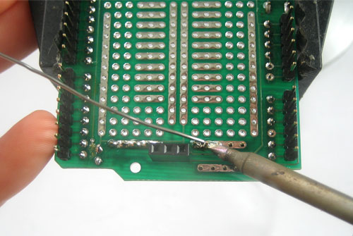
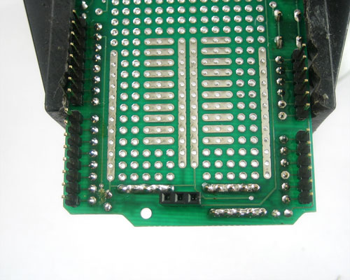
Solder every pin of the male header. Keep the shield on the Arduino to make the job easy.
Once you're done, you can remove the shield from the Arduino.
Etape 18
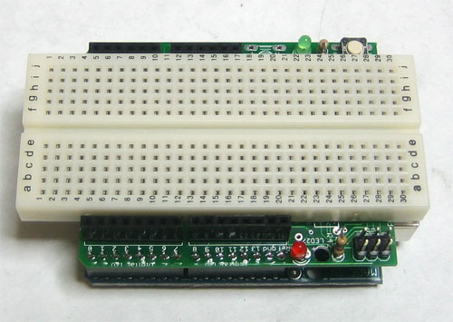
If you're using a half-sized breadboard you should stop now as adding the remaining parts will make the breadboard not fit as well.
Etape 19
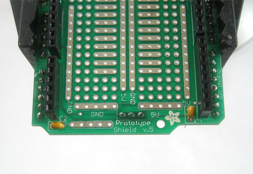
Place the two ceramic capacitors. They are symmetric so you don't have to worry about putting them in backwards.
Etape 20
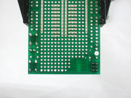
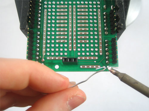
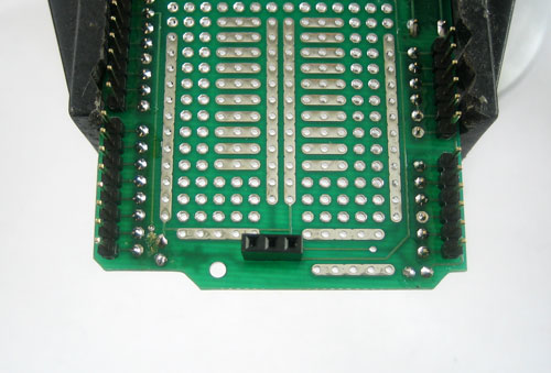
Solder and clip the capacitors (NOTE the image shows a 3pin header but that is not used anymore, ignore it!)
Etape 21
devrait etre vide, renommer les autres points --1
Fichier:ADF-ProtoShield-Souder21.jpg
Etape 22
devrait etre vide, renommer les autres points --1
Fichier:ADF-ProtoShield-Souder22.jpg
Etape 23
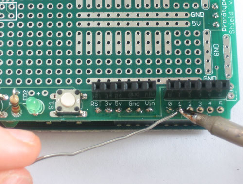
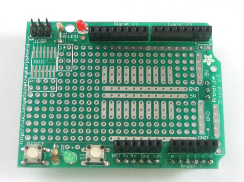
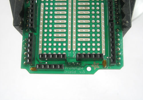
Solder in the 3 5-pin female headers. These are especially useful if you're using a tiny breadboard with the shield.
One of the headers is all ground pins, another is all 5V pins. The final one is 'floating', which means you can use a jumper to make it Vin or 3.3V or any other value you need.
Etape 24
Solder in the headers
(NOTE the image shows a 3pin header but that is not used anymore, ignore it!)
Image a changer, voir page tuto de LadyAda
Traduit avec l'autorisation d'AdaFruit Industries - Translated with the permission from Adafruit Industries - www.adafruit.com
Toute référence, mention ou extrait de cette traduction doit être explicitement accompagné du texte suivant : « Traduction par MCHobby (www.MCHobby.be) - Vente de kit et composants » avec un lien vers la source (donc cette page) et ce quelque soit le média utilisé.
L'utilisation commercial de la traduction (texte) et/ou réalisation, même partielle, pourrait être soumis à redevance. Dans tous les cas de figures, vous devez également obtenir l'accord du(des) détenteur initial des droits. Celui de MC Hobby s'arrêtant au travail de traduction proprement dit.
