ADF-BOARDUINO-SOUDER
Check the kit to verify you have all the parts necessary
Get your tools ready! A board vise, soldering iron & solder , diagonal cutters, and a solder sucker (desoldering tool) if you have one.
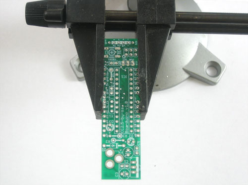
Place the PCB in a vise to make soldering easy!
Heat up the soldering iron to 700 degrees, tin it if necessary.
Make sure the sponge is wetted.
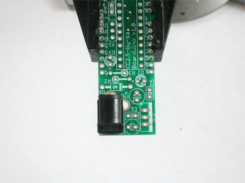
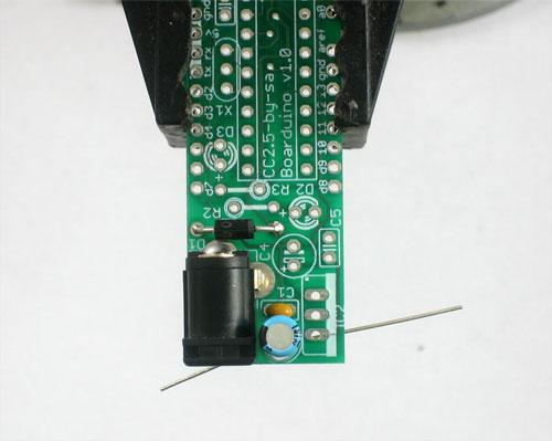
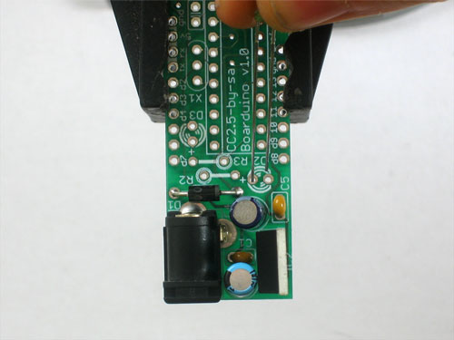
Place the 2.1mm DC jack as shown, it should fit in snugly. Make sure the part is on the top of the board, so that you can see the silkscreened images
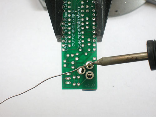
Use the soldering iron to heat up each of the 3 connections and poke the solder in so that it melts into the holes.
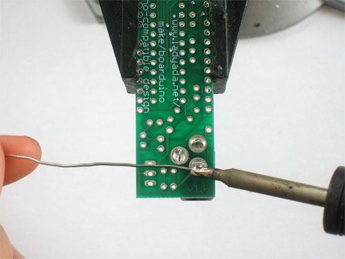
Make sure all three pads are soldered, with plenty of solder, the holes should be filled up. This gives the jack mechanical strength.
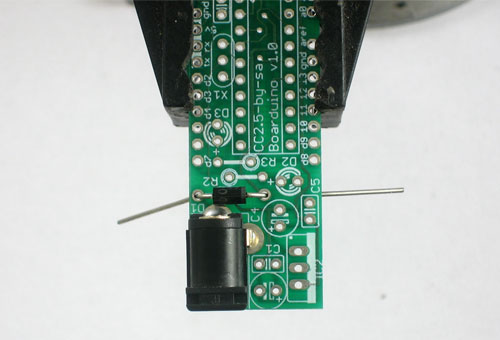
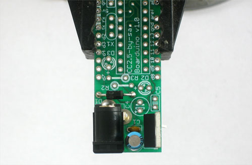
Next, place the 1N4001 diode D1 . Diodes are directional, they only let current flow in one direction. This diode is used to protect the Boarduino from damage. Make sure the white stripe on the diode matches the white stripe in the silkscreened image below. In this picture, the stripe is on the right.
You can bend the leads a bit which will keep the part from falling out when you turn the board over
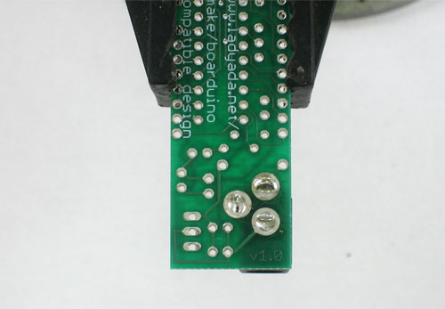
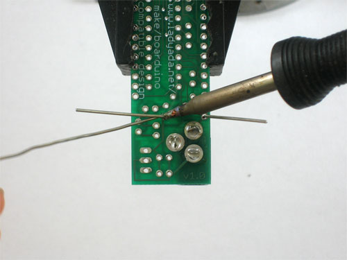
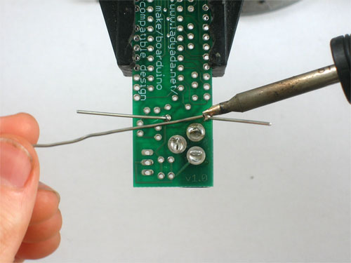
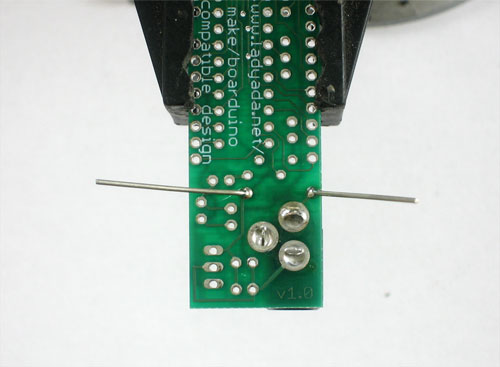
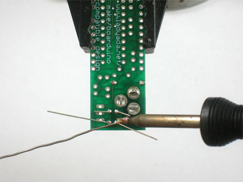
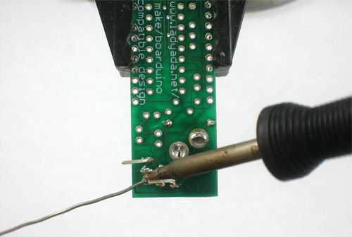
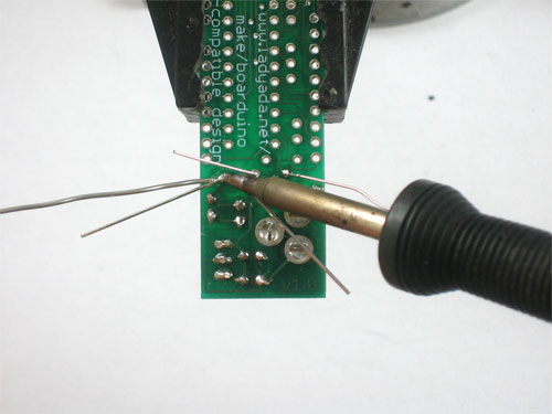
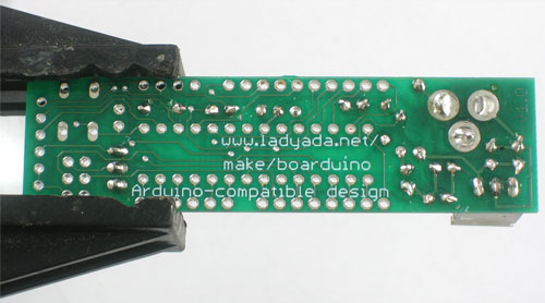
Turn the PCB over and solder both legs so that you get a nice shiny solder joint.
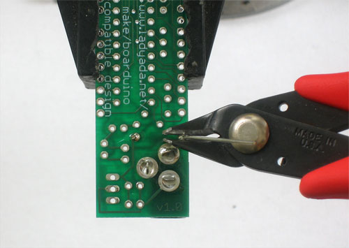
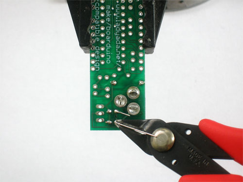
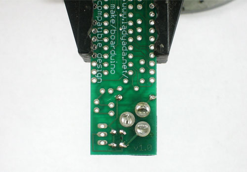
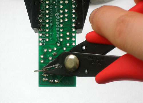
Use the diagonal cutters to clip off the long leads, leaving just a bump.
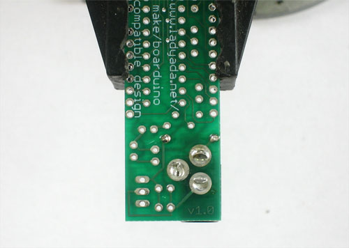
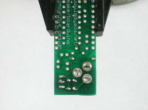
It should look like this
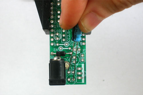
Next, its time to place the 25V electrolytic capacitor C3. Electrolytic capacitors are polarized which means they only work well in one direction. Put it in backwards and they can explode! You can tell how to place it because the silkscreened image has a plus near one hole and the capacitor has one long lead. That lead is the positive lead. In this image, its the one on the right.
Also insert C1 which is a ceramic capacitor. Ceramic capacitors are non-polarized so you don't have to worry about putting it backwards
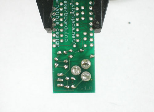
Solder all 4 leads
And clip them short with the cutters.
Next is the 5V regulator. This takes the power from the DC jack which may be something like a 9V battery, and brings it down to 5V, which is suitable for the microcontroller chip. This part must be placed as shown, with the metal heat sink tab on the right.
Turn over the board and solder all three pins, then clip them off
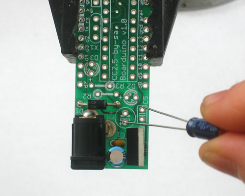
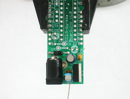
Now you should soder in the 6.3V electrolytic capacitor C4 as shown. Remember its polarized so you must place the longer lead in the positive-marked hole.
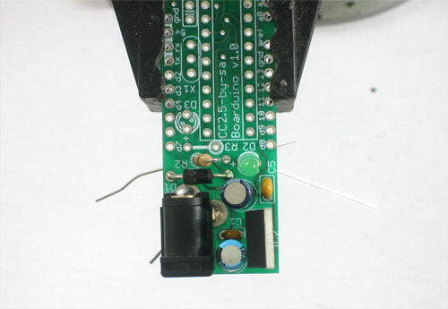
Then place the ceramic capacitor C5
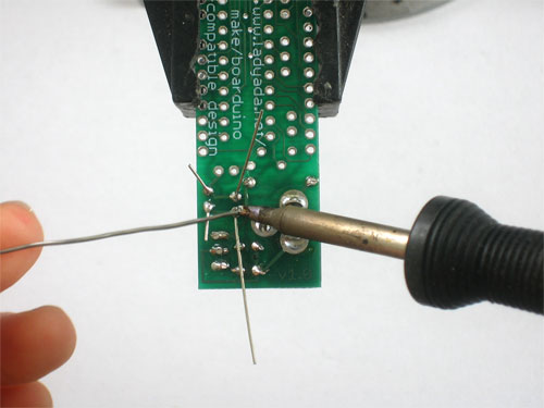
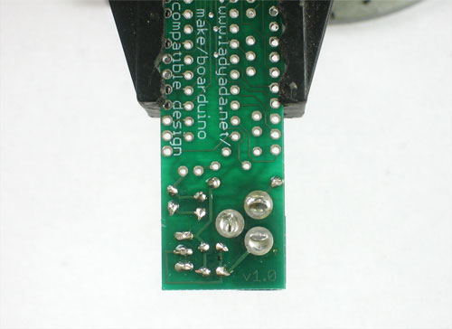
Solder in the capacitors and clip them.
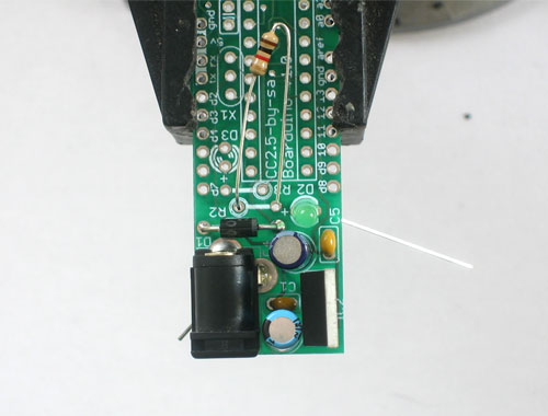
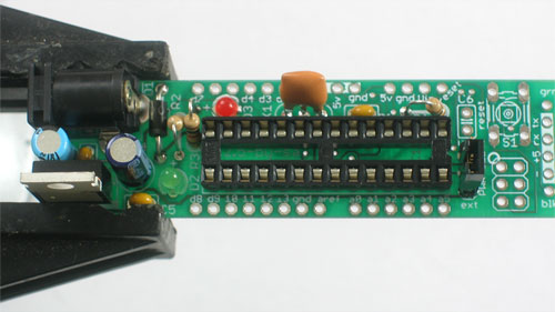
Next is the green 3mm LED D2. Like the electrolytic capacitors, LEDs have polarity and they wont work if soldered in backwards. The long lead is the positive lead, make sure it goes in the hole with a + next to it.
The 1K resistor R2 goes in, its the LED's matching resistor. Bend it over as shown to place it
Solder in the resistor and LED and clip the leads
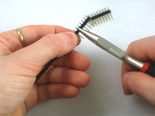
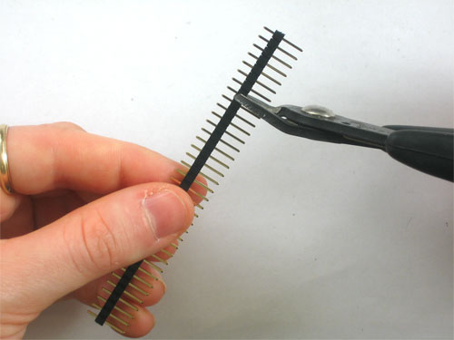
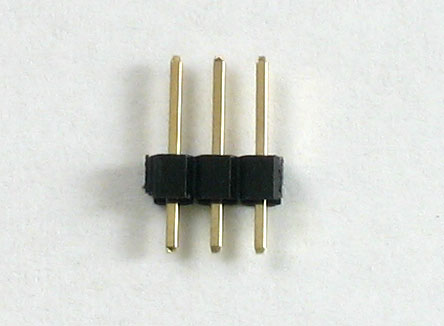
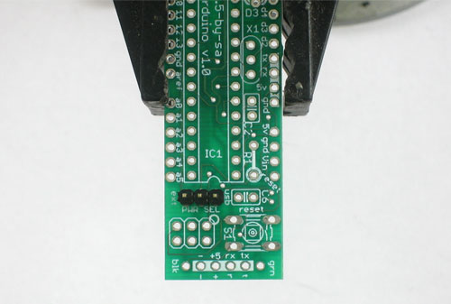
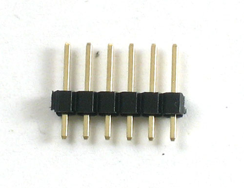
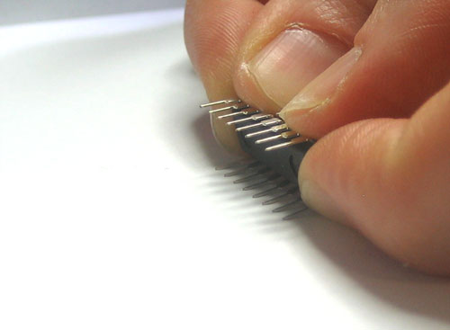
Next you have to make a 3-pin header
Use the diagonal clippers or a pair of pliers to break apart the single row header.
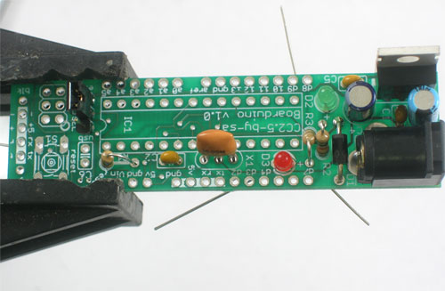
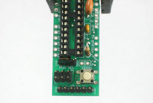
Place the 3 pin header at the other end of the board as shown. the short end goes into the PCB, and the long ends extend up.
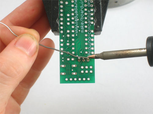
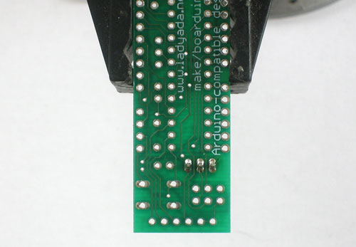
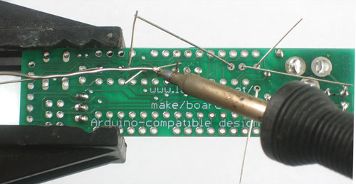
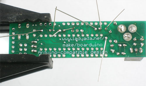
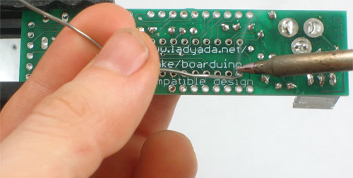
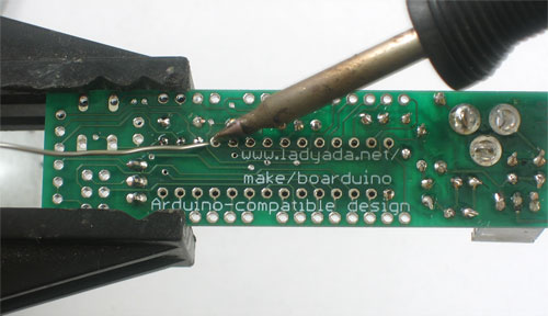
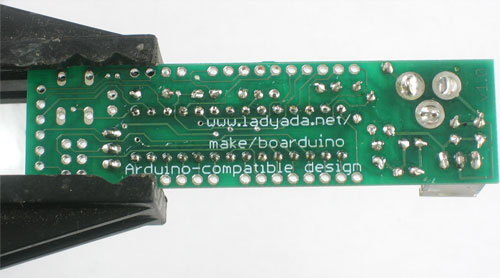
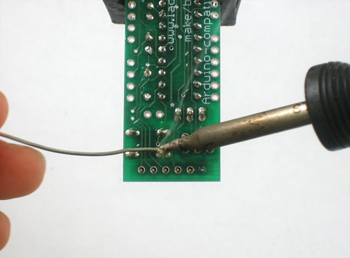
Solder the jumper header in place. You won't need to clip because the leads are short already!
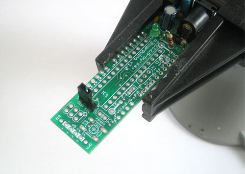
Place the jumper/shunt as shown, so that its on the EXT pair of pins
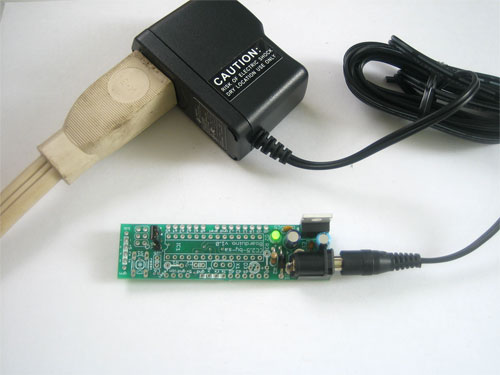
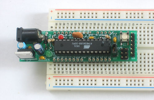
Take the board out of the vise and plug in a power source such as a 9V DC positive-tip wall adapter or a 9V battery with a 2.1mm barrel jack. You should see the green LED light up.
If no LED lights up check: Is the battery or wall adapter good? Is it positive tip? Is the diode in correctly? Is the LED in correctly? Are all the parts in place?
I don't suggest continuing if you can't get the green LED to light as it indicates a problem!
xxx
Fichier:Boarduino-Souder-57.jpg
Fichier:Boarduino-Souder-58.jpg
Fichier:Boarduino-Souder-59.jpg
Fichier:Boarduino-Souder-60.jpg
|
|
En cours de préparation |
Toute référence, mention ou extrait de cette traduction doit être explicitement accompagné du texte suivant : « Traduction par MCHobby (www.MCHobby.be) - Vente de kit et composants » avec un lien vers la source (donc cette page) et ce quelque soit le média utilisé.
L'utilisation commercial de la traduction (texte) et/ou réalisation, même partielle, pourrait être soumis à redevance. Dans tous les cas de figures, vous devez également obtenir l'accord du(des) détenteur initial des droits. Celui de MC Hobby s'arrêtant au travail de traduction proprement dit.
Traduit avec l'autorisation d'AdaFruit Industries - Translated with the permission from Adafruit Industries - www.adafruit.com
