Différences entre versions de « Afficheur LCD-part 2-Breadboard »
| Ligne 4 : | Ligne 4 : | ||
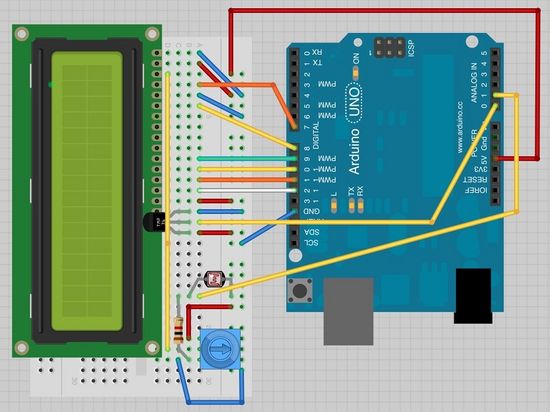
so if you still have this on the breadboard it will simplify things greatly. | so if you still have this on the breadboard it will simplify things greatly. | ||
| − | [[Fichier:afficheur-lcd-part2-montage.jpg| | + | [[Fichier:afficheur-lcd-part2-montage.jpg|550px]] |
There are a few jumper wires that have been moved sightly on this layout. In particular, those near the pot. | There are a few jumper wires that have been moved sightly on this layout. In particular, those near the pot. | ||
Version du 1 janvier 2013 à 20:52
The breadboard layout is based on the layout du tutoriel précédent from lesson 11
,
so if you still have this on the breadboard it will simplify things greatly.
There are a few jumper wires that have been moved sightly on this layout. In particular, those near the pot.
The photocell, 1 kΩ resistor and TMP36 are all new additions to the board. The TMP36 has its curved face towards the display.
Créer par Simon Monk pour AdaFruit
Traduit avec l'autorisation d'AdaFruit Industries - Translated with the permission from Adafruit Industries - www.adafruit.com
Toute référence, mention ou extrait de cette traduction doit être explicitement accompagné du texte suivant : « Traduction par MCHobby (www.MCHobby.be) - Vente de kit et composants » avec un lien vers la source (donc cette page) et ce quelque soit le média utilisé.
L'utilisation commercial de la traduction (texte) et/ou réalisation, même partielle, pourrait être soumis à redevance. Dans tous les cas de figures, vous devez également obtenir l'accord du(des) détenteur initial des droits. Celui de MC Hobby s'arrêtant au travail de traduction proprement dit.
