Différences entre versions de « FEATHER-M0-Brochage »
(Page créée avec « {{FEATHER-M0-NAV}} {{traduction}} {{FEATHER-M0-TRAILER}} ») |
|||
| Ligne 2 : | Ligne 2 : | ||
{{traduction}} | {{traduction}} | ||
| + | |||
| + | == Brochage == | ||
| + | {{ADFImage|FEATHER-M0-Brochage-01.png|640px}}<small><br />Cliquer pour agrandir</small> | ||
| + | |||
| + | The Feather M0 Basic is chock-full of microcontroller goodness. There's also a lot of pins and ports. We'll take you a tour of them now! | ||
| + | |||
| + | {{ADFImage|FEATHER-M0-Brochage-10.jpg|640px}} | ||
| + | |||
| + | {{ADFImage|FEATHER-M0-Brochage-11.jpg|640px}} | ||
| + | |||
| + | == Alimentation == | ||
| + | |||
| + | {{ADFImage|FEATHER-M0-Brochage-20.jpg|640px}} | ||
| + | |||
| + | * '''GND''' - this is the common ground for all power and logic | ||
| + | * '''BAT''' - this is the positive voltage to/from the JST jack for the optional Lipoly battery | ||
| + | * '''USB''' - this is the positive voltage to/from the micro USB jack if connected | ||
| + | * '''EN''' - this is the 3.3V regulator's enable pin. It's pulled up, so connect to ground to disable the 3.3V regulator | ||
| + | * '''3V''' - this is the output from the 3.3V regulator, it can supply 500mA peak | ||
| + | |||
| + | == Logique de commande == | ||
| + | This is the general purpose I/O pin set for the microcontroller. | ||
| + | * '''All logic is 3.3V''' | ||
| + | * '''All pins can do PWM output''' | ||
| + | * '''All pins can be interrupt inputs''' | ||
| + | |||
| + | Les broches spécifiques | ||
| + | * '''#0 / RX''' - GPIO #0, also receive (input) pin for Serial1 (hardware UART), also can be analog input | ||
| + | * '''#1 / TX''' - GPIO #1, also transmit (output) pin for Serial1, also can be analog input | ||
| + | * '''#20 / SDA''' - GPIO #20, also the I2C (Wire) data pin. There's no pull up on this pin by default so when using with I2C, you may need a 2.2K-10K pullup. | ||
| + | * '''#21 / SCL''' - GPIO #21, also the I2C (Wire) clock pin. There's no pull up on this pin by default so when using with I2C, you may need a 2.2K-10K pullup. | ||
| + | * '''#5''' - GPIO #5 | ||
| + | * '''#6''' - GPIO #6 | ||
| + | * '''#9''' - GPIO #9, also analog input A7. This analog input is connected to a voltage divider for the lipoly battery so be aware that this pin naturally 'sits' at around 2VDC due to the resistor divider | ||
| + | * '''#10'' - GPIO #10 | ||
| + | * '''#11''' - GPIO #11 | ||
| + | * '''#12''' - GPIO #12 | ||
| + | * '''#13''' - GPIO #13 and is connected to the red LED next to the USB jack | ||
| + | * '''A0''' - This pin is analog input A0 but is also an analog output due to having a DAC (digital-to-analog converter). You can set the raw voltage to anything from 0 to 3.3V, unlike PWM outputs this is a true analog output | ||
| + | * '''A1 à A5''' - These are each analog input as well as digital I/O pins. | ||
| + | * '''SCK/MOSI/MISO (GPIO 24/23/22)''' - These are the hardware SPI pins, you can use them as everyday GPIO pins (but recommend keeping them free as they are best used for hardware SPI connections for high speed. | ||
| + | |||
| + | == Les autres broches == | ||
| + | |||
| + | * '''RST''' - this is the Reset pin, tie to ground to manually reset the AVR, as well as launch the bootloader manually | ||
| + | * '''ARef''' - the analog reference pin. Normally the reference voltage is the same as the chip logic voltage (3.3V) but if you need an alternative analog reference, connect it to this pin and select the external AREF in your firmware. Can't go higher than 3.3V! | ||
| + | |||
| + | {{ADFImage|FEATHER-M0-Brochage-30.jpg|640px}} | ||
| + | |||
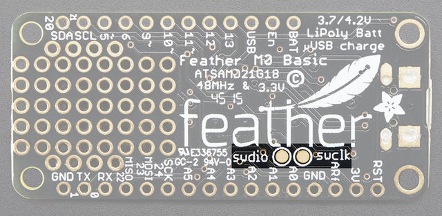
| + | * '''SWCLK & SWDIO''' - These pads on the bottom are used to program the chip. They can also be connected to an SWD debugger. | ||
| + | |||
| + | {{ADFImage|FEATHER-M0-Brochage-31.jpg|640px}} | ||
{{FEATHER-M0-TRAILER}} | {{FEATHER-M0-TRAILER}} | ||
Version du 25 avril 2016 à 16:00
|
|
En cours de traduction/élaboration. |
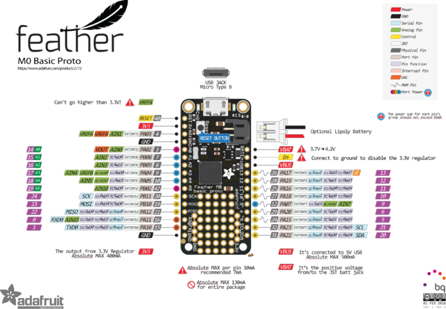
Brochage
Crédit: AdaFruit Industries www.adafruit.com
Cliquer pour agrandir
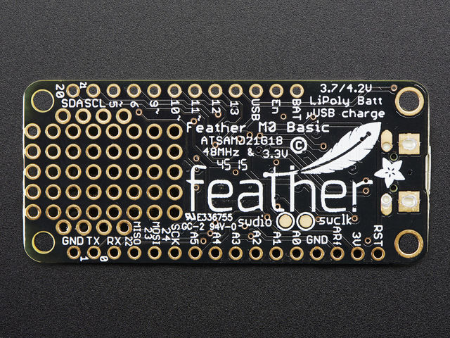
The Feather M0 Basic is chock-full of microcontroller goodness. There's also a lot of pins and ports. We'll take you a tour of them now!
640px
Crédit: AdaFruit Industries www.adafruit.com
Crédit: AdaFruit Industries www.adafruit.com
Alimentation
Crédit: AdaFruit Industries www.adafruit.com
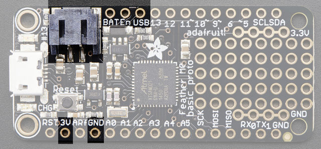
- GND - this is the common ground for all power and logic
- BAT - this is the positive voltage to/from the JST jack for the optional Lipoly battery
- USB - this is the positive voltage to/from the micro USB jack if connected
- EN - this is the 3.3V regulator's enable pin. It's pulled up, so connect to ground to disable the 3.3V regulator
- 3V - this is the output from the 3.3V regulator, it can supply 500mA peak
Logique de commande
This is the general purpose I/O pin set for the microcontroller.
- All logic is 3.3V
- All pins can do PWM output
- All pins can be interrupt inputs
Les broches spécifiques
- #0 / RX - GPIO #0, also receive (input) pin for Serial1 (hardware UART), also can be analog input
- #1 / TX - GPIO #1, also transmit (output) pin for Serial1, also can be analog input
- #20 / SDA - GPIO #20, also the I2C (Wire) data pin. There's no pull up on this pin by default so when using with I2C, you may need a 2.2K-10K pullup.
- #21 / SCL - GPIO #21, also the I2C (Wire) clock pin. There's no pull up on this pin by default so when using with I2C, you may need a 2.2K-10K pullup.
- #5 - GPIO #5
- #6 - GPIO #6
- #9 - GPIO #9, also analog input A7. This analog input is connected to a voltage divider for the lipoly battery so be aware that this pin naturally 'sits' at around 2VDC due to the resistor divider
- '#10 - GPIO #10
- #11 - GPIO #11
- #12 - GPIO #12
- #13 - GPIO #13 and is connected to the red LED next to the USB jack
- A0 - This pin is analog input A0 but is also an analog output due to having a DAC (digital-to-analog converter). You can set the raw voltage to anything from 0 to 3.3V, unlike PWM outputs this is a true analog output
- A1 à A5 - These are each analog input as well as digital I/O pins.
- SCK/MOSI/MISO (GPIO 24/23/22) - These are the hardware SPI pins, you can use them as everyday GPIO pins (but recommend keeping them free as they are best used for hardware SPI connections for high speed.
Les autres broches
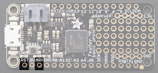
- RST - this is the Reset pin, tie to ground to manually reset the AVR, as well as launch the bootloader manually
- ARef - the analog reference pin. Normally the reference voltage is the same as the chip logic voltage (3.3V) but if you need an alternative analog reference, connect it to this pin and select the external AREF in your firmware. Can't go higher than 3.3V!
Crédit: AdaFruit Industries www.adafruit.com
- SWCLK & SWDIO - These pads on the bottom are used to program the chip. They can also be connected to an SWD debugger.
Crédit: AdaFruit Industries www.adafruit.com
Source: Adafruit Feather M0 Basic Proto créé par LadyAda pour AdaFruit Industries. Crédit [www.adafruit.com AdaFruit Industries]
Traduit par Meurisse D. pour MCHobby.be
Traduit avec l'autorisation d'AdaFruit Industries - Translated with the permission from Adafruit Industries - www.adafruit.com
Toute référence, mention ou extrait de cette traduction doit être explicitement accompagné du texte suivant : « Traduction par MCHobby (www.MCHobby.be) - Vente de kit et composants » avec un lien vers la source (donc cette page) et ce quelque soit le média utilisé.
L'utilisation commercial de la traduction (texte) et/ou réalisation, même partielle, pourrait être soumis à redevance. Dans tous les cas de figures, vous devez également obtenir l'accord du(des) détenteur initial des droits. Celui de MC Hobby s'arrêtant au travail de traduction proprement dit.