MP6500
Présentation
xxx
Détails techniques
xxx
Utiliser le pilote
Alimentation
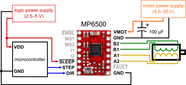
The driver requires a motor supply voltage of 4.5 V to 35 V to be connected across VMOT and GND. This supply should have appropriate decoupling capacitors close to the board, and it should be capable of delivering the expected stepper motor current. The driver has an internal voltage regulator, so it does not require a logic voltage supply.
| This carrier board uses low-ESR ceramic capacitors, which makes it susceptible to destructive LC voltage spikes, especially when using power leads longer than a few inches. Under the right conditions, these spikes can exceed the 40 V absolute maximum voltage rating for the MP6500 and permanently damage the board, even when the motor supply voltage is as low as 12 V. One way to protect the driver from such spikes is to put a large (at least 47 µF) electrolytic capacitor across motor power (VMOT) and ground somewhere close to the board. |
Connexion moteur
Four, six, and eight-wire stepper motors can be driven by the MP6500 if they are properly connected; a FAQ answer (Pololu, anglais) explains the proper wirings in detail.
| Warning: Connecting or disconnecting a stepper motor while the driver is powered can destroy the driver. (More generally, rewiring anything while it is powered is asking for trouble.) |
Vitesse et Micro-stepping
Warning: Connecting or disconnecting a stepper motor while the driver is powered can destroy the driver. (More generally, rewiring anything while it is powered is asking for trouble.)
| MS1 | MS2 | Résolution Microstep |
| bas | bas | Full step (Pas complet) |
| haut | bas | Half-step (Demi pas, 1/2) |
| bas | haut | Quarter-step (Quart de pas, 1/4) |
| high | high | Heighth-step (huitième de pas, 1/8) |
Entrées de contrôle
Each pulse to the STEP input corresponds to one microstep of the stepper motor in the direction selected by the DIR pin. These inputs are both pulled low by default through internal 500 kΩ pull-down resistors. If you just want rotation in a single direction, you can leave DIR disconnected.
The chip has two different inputs for controlling its power states: SLEEP and ENBL x. For details about these power states, see the datasheet. Please note that the driver pulls both of these pins low through internal 500 kΩ pull-down resistors. The default SLEEP state prevents the driver from operating; this pin must be high to enable the driver (it can be connected directly to a logic “high” voltage between 2.5 V and 5 V, or it can be dynamically controlled by connecting it to a digital output of an MCU). The default state of the ENBL pin is to enable the driver, so this pin can be left disconnected.
Où Acheter
Vous trouverez également les produits suivants:
A voir aussi
Documentation réalisée par Meurisse. D pour MCHobby.be. En partie basé sur les informations disponible sur le site de Pololu
Traduit avec l'autorisation de Pololu - Translated with the permission from Pololu - www.pololu.com
Toute référence, mention ou extrait de cette traduction doit être explicitement accompagné du texte suivant : « Traduction par MCHobby (www.MCHobby.be) - Vente de kit et composants » avec un lien vers la source (donc cette page) et ce quelque soit le média utilisé.
L'utilisation commercial de la traduction (texte) et/ou réalisation, même partielle, pourrait être soumis à redevance. Dans tous les cas de figures, vous devez également obtenir l'accord du(des) détenteur initial des droits. Celui de MC Hobby s'arrêtant au travail de traduction proprement dit.
