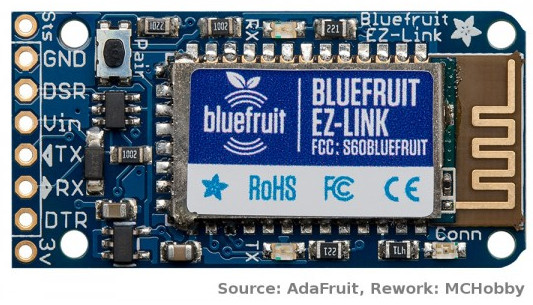
Modèle:EZ-LINK-PINOUT
Révision datée du 19 juin 2014 à 20:29 par Admin (discussion | contributions) (→Connecteur principal (type FTDI))
Intro
Bluefruit EZ-Link est une liaison série avec un connecteur semblable à un "FTDI", ce qui permet de l'utiliser directement avec des produits disposant d'un connecteur FTDI. Vous pouvez également le brancher sur un breadboard ou faire vos raccordements/soudures directement sur le Bluefruit (en fonction de vos besoins).
Il y a cependant quelques changements mineurs, de sorte que vous devriez vous pencher pendant quelques minutes sur la définition de chaque broche.
Connecteur principal (type FTDI)
- GND: C'est la broche de masse commune, utilisée comme référence de masse pour l'alimentation et les signaux. Assurez-vous que toutes les masses de votre montage soient commune entre le microcontrôleur, aliementation, accis et EZ-Link.
- DSR: est la broche de contrôle de flux matériel "Data Signal Ready". Signal envoyé par le microcontrôleur vers l'ordinateur/hotes appairé via l'EZ-Link. C'est la broche de signal à utiliser si vous voulez envoyer un signal depuis l'UART vers l'ordinateur/hôte appairé. L'ordinateur appairé poura alir lire le statut de la ligne terminal (terminal-status lines).
Il ne s'agit pas d'une ligne à grande vitesse, comptez sur un délai de 100ms entre le moment où la le signal est basculé et le moment où il est lisible sur l'ordinateur appairé.
Raccordez ce signal à la masse si vous n'utilisez pas ce signal.
Sur un câble FTDI, le signal est souvent libellé CTS (Clear To Send) pour une ligne de contrôle différente. Bluetooth ne dispose pas de support pour renvoyer un signal vers l'ordinateur appairé... raison pour laquelle Adafruit lui a substitué le signal DSR. - Vin: This is the power pin into the Bluefruit module, it passes through a 3.3V regulator so this voltage can be from 3.3V to 16VDC and is reverse-polarity protected. If a battery is connected via the optional JST connector on the back, this pin becomes an output so you can power your microcontroller/project via the battery.
If you plan to use the optional JST connector on the back, don't provide power to this pin from the microcontroller - TX: This is the serial UART output pin that is transmitted from the paired computer, wirelessly to the Bluefruit and out this pin. It is 3V logic level so you can use it with 3 or 5V microcontrollers.
- RX: This is the serial UART input pin that is transmitted from the microcontroller into the EZ-Link then sent wirelessly to the computer. It is level shifted so you can use 3 or 5V logic microcontrollers/signal
- DTR: This is the "Data Terminal Ready" hardware flow control pin that is sent from the paired computer to the microcontroller. Often this is used for telling the client that the server is ready to send data. However, this pin tends to be used for reprogramming Arduino microcontrollers by connecting it to the reset line. The Arduino IDE toggles this pin up and down to reset the Arduino to start the bootloader before uploading code. This pin is 3V output so you can use it with 3 or 5V
Broches en extra
On either side of the 'classic FTDI' header, we added two additional pins you may find useful
- 3V: this is the 3.3V output from the onboard voltage regulator. If you power the module from the optional JST jack or Vin pin, and that voltage is 3.5V or higher, you can grab a nice regulated 3.3V up to 100mA from this pin
- Sts: this is the Connection Status pin, when it is 0V, the UART is not 'open' on the other side. When it is 3V, that means the bluetooth UART is 'open' on the computer. Normally the DTR pin would be used for this kind of status but since the DTR pin is used for resetting Arduino's, we have a different pin for this purpose.
