Différences entre versions de « Photo-résistance »
| Ligne 51 : | Ligne 51 : | ||
== Qu'est ce donc qu'un lux? == | == Qu'est ce donc qu'un lux? == | ||
| − | La plupart des fiches techniques utilisent le [http://en.wikipedia.org/wiki/Lux lux] pour indiquer la résistance correspondant à un certain niveau lumineux. Mais qu'est ce que c'est qu'un [http://en.wikipedia.org/wiki/Lux lux] ? | + | La plupart des fiches techniques utilisent le [http://en.wikipedia.org/wiki/Lux lux] pour indiquer la résistance correspondant à un certain niveau lumineux. Mais qu'est ce que c'est qu'un [http://en.wikipedia.org/wiki/Lux lux] ? Ce n'est pas une méthode que nous utilisons habituellement pour décrire la luminosité. C'est donc une unité difficile à évaluer. |
| + | |||
| + | Voici une table issue de Wikipedia permettant d'établir un correspondance entre Lux et Luminosité! | ||
{| class="wikitable" border="1" | {| class="wikitable" border="1" | ||
|- | |- | ||
| − | | align="center" width="400" | | + | | align="center" width="400" | Luminosité |
| − | | align="center" width="400" | | + | | align="center" width="400" | Exemple |
|- style="font-size: 90%" | |- style="font-size: 90%" | ||
| align="left" | 0.002 lux | | align="left" | 0.002 lux | ||
| − | | align="left" | | + | | align="left" | Nuit par temps clair sans lune. |
|- style="font-size: 90%" | |- style="font-size: 90%" | ||
| align="left" | 0.2 lux | | align="left" | 0.2 lux | ||
| − | | align="left" | | + | | align="left" | Minimum de lumière que doit produire un éclairage d'urgence (AS2293). |
|- style="font-size: 90%" | |- style="font-size: 90%" | ||
| align="left" | 0.27 - 1 lux | | align="left" | 0.27 - 1 lux | ||
| − | | align="left" | | + | | align="left" | Pleine lune par temps clair. |
|- style="font-size: 90%" | |- style="font-size: 90%" | ||
| align="left" | 3.4 lux | | align="left" | 3.4 lux | ||
| − | | align="left" | | + | | align="left" | Limite crépusculaire (sombre) au couché du soleil en zone urbaine. |
|- style="font-size: 90%" | |- style="font-size: 90%" | ||
| align="left" | 50 lux | | align="left" | 50 lux | ||
| − | | align="left" | | + | | align="left" | Eclairage d'un living room |
|- style="font-size: 90%" | |- style="font-size: 90%" | ||
| align="left" | 80 lux | | align="left" | 80 lux | ||
| − | | align="left" | | + | | align="left" | Eclairage des toilette/Hall |
|- style="font-size: 90%" | |- style="font-size: 90%" | ||
| align="left" | 100 lux | | align="left" | 100 lux | ||
| − | | align="left" | | + | | align="left" | Journée très sombre/temps très couvert. |
|- style="font-size: 90%" | |- style="font-size: 90%" | ||
| align="left" | 300 - 500 lux | | align="left" | 300 - 500 lux | ||
| − | | align="left" | | + | | align="left" | Levé du soleil, luminosité par temps clair. Zone de bureau correctement éclairée. |
|- style="font-size: 90%" | |- style="font-size: 90%" | ||
| align="left" | 1,000 lux | | align="left" | 1,000 lux | ||
| − | | align="left" | | + | | align="left" | Temps couvert; Eclairage typique d'un studio TV |
|- style="font-size: 90%" | |- style="font-size: 90%" | ||
| align="left" | 10,000 - 25,000 lux | | align="left" | 10,000 - 25,000 lux | ||
| − | | align="left" | | + | | align="left" | Pleine journée (pas de soleil direct) |
|- style="font-size: 90%" | |- style="font-size: 90%" | ||
| align="left" | 32,000 - 130,000 lux | | align="left" | 32,000 - 130,000 lux | ||
| − | | align="left" | | + | | align="left" | Soleil direct |
|} | |} | ||
Version du 17 mai 2012 à 11:47
|
|
En cours de traduction |
Qu'est ce qu'une photorésistance?
Les photorésistances (PhotoCells ou CdS en anglais) sont des senseurs qui permettent de détecter la lumière. elles sont petites, bon marchés, économiques en énergies, faciles à utiliser et ne s'usent pas.
C'est pour ces raisons qu'elles apparaissent souvent dans les jouets, gadgets et appareils. Elles sont souvent identifiés sous la dénomination CdS (parce qu'elles sont faites de Cadmium-Sulfite), LDR (pour Light Dependant Resistor ce qui signifie Résistance dépendant de la lumière et Photo-résistance/photorésistance.
Fondamentalement, les photorésistances sont des résistance dont la valeur résistive (en ohms Ω) change en fonction de la quantité de lumière qui atteind le capteur (la partie en serpentin sur le dessus). Elles sont abordables (bon marchés), existent sous de nombreux formats/tailles, disponibles sous de nombreuses spécifications (caractéristiques) mais sont très imprécises.
Chaque photo-résistance agit un peu différemment d'une autre, même lorsqu'elles proviennent du même processus de fabrication. La variation peut-être vraiment grande, 50% voire plus!
C'est pour cette raison qu'elle ne doivent pas être utilisées pour déterminer précisément le niveau lumineux en lux ou milli-candela. A la place, vous pourrez être capable de détecter des variations de lumières élémentaires.
La plupart des applications sensible à la lumière tel que "il fait noir", "il fait clair", "y a t'il quelque-chose en face du senseur (qui bloque la lumière)", "y a t'il quelque-chose qui interrompt le faisceau laser" (senseur d'interruption du faisceau) ou "senseur multiple pour détecter la direction/source de la lumière" sont des cas ou l'utilisation d'une photo-résistance est approprié.
Quelques données techniques
- Etandue de la variation de résistance: de 200K Ω (noir) à 10KΩ (luminosité de 10 lux)
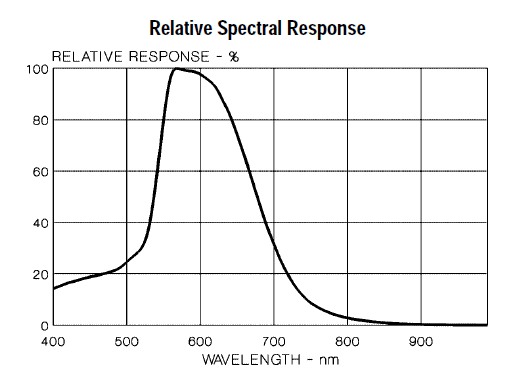
- Sensibilité: Les photo-résistances répondent à des lumières de longueur d'onde variant entre 400nm (violet) et 600nm (orange), avec un pic à ~520nm (vert).
- Alimentation: Presque tout type de tension jusqu'à 100V, consomme moins de 1mA en moyenne (cela dépend de la tension d'alimentation utilisée)
Problèmes en utilisation multi-senseur...
Si vous utilisez plusieurs senseurs, vous pourriez rencontrer quelques problèmes.
Si vous ajoutez plusieurs senseur, vous pourriez remarquer que la température (détection de niveau lumineux) est inconstante. Cela indique que les senseurs interfèrent les un avec les autres lorsque vous passer la lecture analogique d'une broche à l'autre.
Cela peut être corrigé en faisant deux lectures (avec pause et ignorant le résultat de la première lecture) sur le premier senseur. Cette méthode est décrite dans l'article "How to multiplex analog readings what can go wrong with high impedance sensors and how to fix it".
En effet, si le senseur présente une haute impédance et qu'il y a une capacitance (capacité ou toute sorte de matériel équivalent) sur le convertisseur ADC, cela prendra un certain temps pour que la capacitance se charge. Raison de la première lecture erronée :-)
Comment mesurer la lumière avec une photo-résistance
Comme précisé, la résistance d'une cellule photo-résistive change lorsque sa surface est exposée à plus de lumière.
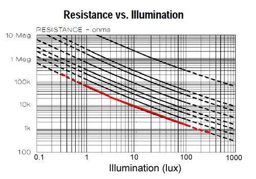
- Lorsqu'il fait SOMBRE, le senseur se "ressemble" à une grande résistance (jusqu'à 10MΩ)
- Lorsque le niveau lumineux augmente, la résistance diminue.
Le graphique ci-dessous indique approximativement la résistance du senseur sous différents niveaux d'illumination. Souvenez vous que chaque photo-résistance est diffère des autres. Ce graphique est seulement un guide!
Notez que le graphe n'est pas linéaire mais logarithmique.
Les photo-résistances, particulièrement les plus faciles à trouver et donc les plus communes, ne sont pas sensible à toutes les lumières. En particulier, elle tendent à être sensibles à des lumières entre 700nm (rouge) et 500nm (vert).
Fondamentalement, la lumière bleue ne sera pas aussi efficace pour activer le senseur qu'une lumière verte/jaune!
Qu'est ce donc qu'un lux?
La plupart des fiches techniques utilisent le lux pour indiquer la résistance correspondant à un certain niveau lumineux. Mais qu'est ce que c'est qu'un lux ? Ce n'est pas une méthode que nous utilisons habituellement pour décrire la luminosité. C'est donc une unité difficile à évaluer.
Voici une table issue de Wikipedia permettant d'établir un correspondance entre Lux et Luminosité!
| Luminosité | Exemple |
| 0.002 lux | Nuit par temps clair sans lune. |
| 0.2 lux | Minimum de lumière que doit produire un éclairage d'urgence (AS2293). |
| 0.27 - 1 lux | Pleine lune par temps clair. |
| 3.4 lux | Limite crépusculaire (sombre) au couché du soleil en zone urbaine. |
| 50 lux | Eclairage d'un living room |
| 80 lux | Eclairage des toilette/Hall |
| 100 lux | Journée très sombre/temps très couvert. |
| 300 - 500 lux | Levé du soleil, luminosité par temps clair. Zone de bureau correctement éclairée. |
| 1,000 lux | Temps couvert; Eclairage typique d'un studio TV |
| 10,000 - 25,000 lux | Pleine journée (pas de soleil direct) |
| 32,000 - 130,000 lux | Soleil direct |
Connecting to your photocell
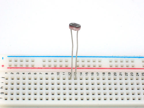
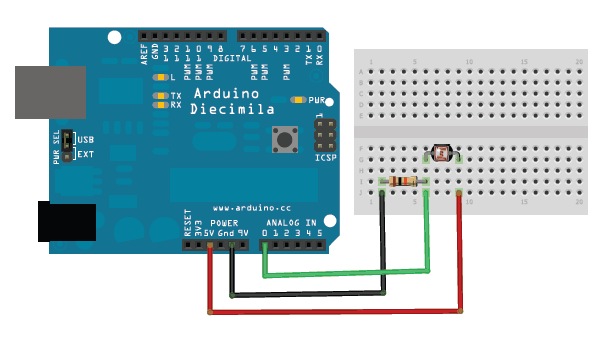
Because photocells are basically resistors, they are non-polarized. That means you can connect them up 'either way' and they'll work just fine!
Photocells are pretty hardy, you can easily solder to them, clip the leads, plug them into breadboards, use alligator clips, etc. The only care you should take is to avoid bending the leads right at the epoxied sensor, as they could break off if flexed too often.
Analog voltage reading method
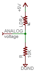
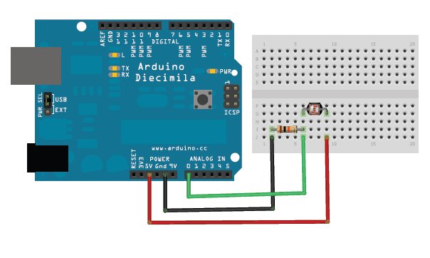
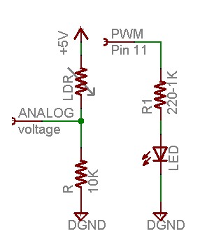
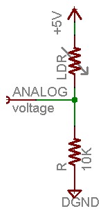
The easiest way to measure a resistive sensor is to connect one end to Power and the other to a pull-down resistor to ground. Then the point between the fixed pulldown resistor and the variable photocell resistor is connected to the analog input of a microcontroller such as an Arduino (shown)
For this example I'm showing it with a 5V supply but note that you can use this with a 3.3v supply just as easily. In this configuration the analog voltage reading ranges from 0V (ground) to about 5V (or about the same as the power supply voltage).
The way this works is that as the resistance of the photocell decreases, the total resistance of the photocell and the pulldown resistor decreases from over 600KΩ to 10KΩ. That means that the current flowing through both resistors increases which in turn causes the voltage across the fixed 10KΩ resistor to increase. Its quite a trick!
| Ambient light like... | Ambient light (lux) | Photocell resistance (Ohms) | LDR + R (Ohms) | Current thru LDR +R | Voltage across R |
| Dim hallway | 0.1 lux | 600 KOhms | 610 KOhms | 0.008 mA | 0.1 V |
| Moonlit night | 1 lux | 70 KOhms | 80 KOhms | 0.07 mA | 0.6 V |
| Dark room | 10 lux | 10 KOhms | 20 KOhms | 0.25 mA | 2.5 V |
| Dark overcast day / Bright room | 100 lux | 1.5 KOhms | 11.5 KOhms | 0.43 mA | 4.3 V |
| Overcast day | 1000 lux | 300 Ohms | 10.03 KOhms | 0.5 mA | 5V |
This table indicates the approximate analog voltage based on the sensor light/resistance w/a 5V supply and 10KΩ pulldown resistor
If you're planning to have the sensor in a bright area and use a 10KΩ pulldown, it will quickly saturate. That means that it will hit the 'ceiling' of 5V and not be able to differentiate between kinda bright and really bright. In that case, you should replace the 10KΩ pulldown with a 1KΩ pulldown. In that case, it will not be able to detect dark level differences as well but it will be able to detect bright light differences better. This is a tradeoff that you will have to decide upon!
| Ambient light like... | Ambient light (lux) | Photocell resistance (Ohms) | LDR + R (Ohms) | Current thru LDR+R | Voltage across R |
| Moonlit night | 1 lux | 70 KOhms | 71 KOhms | 0.07 mA | 0.1 V |
| Dark room | 10 lux | 10 KOhms | 11 KOhms | 0.45 mA | 0.5 V |
| Dark overcast day / Bright room | 100 lux | 1.5 KOhms | 2.5 KOhms | 2 mA | 2.0 V |
| Overcast day | 1000 lux | 300 Ohms | 1.3 KOhms | 3.8 mA | 3.8 V |
| Full daylight | 10,000 lux | 100 Ohms | 1.1 KOhms | 4.5 mA | 4.5 V |
This table indicates the approximate analog voltage based on the sensor light/resistance w/a 5V supply and 1K pulldown resistor
Note that our method does not provide linear voltage with respect to brightness! Also, each sensor will be different. As the light level increases, the analog voltage goes up even though the resistance goes down:
Vo = Vcc ( R / (R + Photocell) )
That is, the voltage is proportional to the inverse of the photocell resistance which is, in turn, inversely proportional to light levels.
Simple demonstration of use
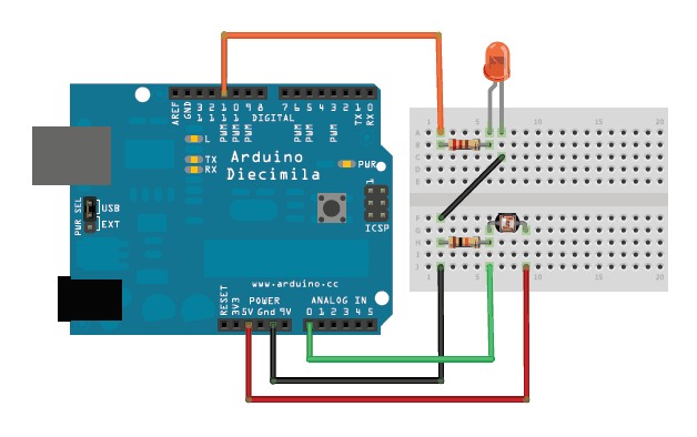
This sketch will take the analog voltage reading and use that to determine how bright the red LED is. The darker it is, the brighter the LED will be! Remember that the LED has to be connected to a PWM pin for this to work, I use pin 11 in this example.
These examples assume you know some basic Arduino programming. If you don't, maybe spend some time reviewing the basics at the Arduino tutorial?
 /* Photocell simple testing sketch.

Connect one end of the photocell to 5V, the other end to Analog 0.
Then connect one end of a 10K resistor from Analog 0 to ground
Connect LED from pin 11 through a resistor to ground
For more information see www.ladyada.net/learn/sensors/cds.html */

int photocellPin = 0;     // the cell and 10K pulldown are connected to a0
int photocellReading;     // the analog reading from the sensor divider
int LEDpin = 11;          // connect Red LED to pin 11 (PWM pin)
int LEDbrightness;        //
void setup(void) {
  // We'll send debugging information via the Serial monitor
  Serial.begin(9600);
}

void loop(void) {
  photocellReading = analogRead(photocellPin);

  Serial.print("Analog reading = ");
  Serial.println(photocellReading);     // the raw analog reading

  // LED gets brighter the darker it is at the sensor
  // that means we have to -invert- the reading from 0-1023 back to 1023-0
  photocellReading = 1023 - photocellReading;
  //now we have to map 0-1023 to 0-255 since thats the range analogWrite uses
  LEDbrightness = map(photocellReading, 0, 1023, 0, 255);
  analogWrite(LEDpin, LEDbrightness);

  delay(100);
}
You may want to try different pulldown resistors depending on the light level range you want to detect!
Simple code for analog light measurements
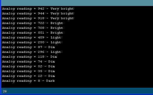
This code doesn't do any calculations, it just prints out what it interprets as the amount of light in a qualitative manner. For most projects, this is pretty much all thats needed!
/* Photocell simple testing sketch.

Connect one end of the photocell to 5V, the other end to Analog 0.
Then connect one end of a 10K resistor from Analog 0 to ground

For more information see www.ladyada.net/learn/sensors/cds.html */

int photocellPin = 0;     // the cell and 10K pulldown are connected to a0
int photocellReading;     // the analog reading from the analog resistor divider

void setup(void) {
  // We'll send debugging information via the Serial monitor
  Serial.begin(9600);
}

void loop(void) {
  photocellReading = analogRead(photocellPin);

  Serial.print("Analog reading = ");
  Serial.print(photocellReading);     // the raw analog reading

  // We'll have a few threshholds, qualitatively determined
  if (photocellReading < 10) {
    Serial.println(" - Dark");
  } else if (photocellReading < 200) {
    Serial.println(" - Dim");
  } else if (photocellReading < 500) {
    Serial.println(" - Light");
  } else if (photocellReading < 800) {
    Serial.println(" - Bright");
  } else {
    Serial.println(" - Very bright");
  }
  delay(1000);
}
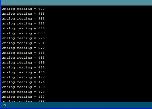
To test it, I started in a sunlit (but shaded) room and covered the sensor with my hand, then covered it with a piece of blackout fabric.
BONUS! Reading photocells without analog pins
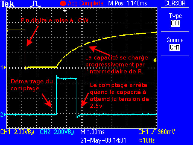
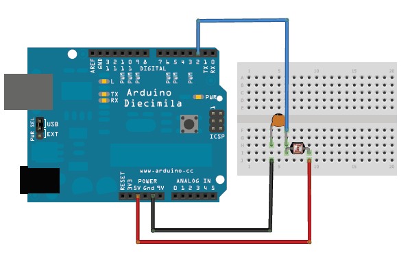
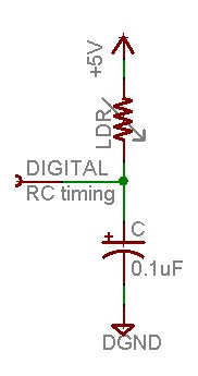
Because photocells are basically resistors, its possible to use them even if you don't have any analog pins on your microcontroller (or if say you want to connect more than you have analog input pins). The way we do this is by taking advantage of a basic electronic property of resistors and capacitors. It turns out that if you take a capacitor that is initially storing no voltage, and then connect it to power (like 5V) through a resistor, it will charge up to the power voltage slowly. The bigger the resistor, the slower it is.
This capture from an oscilloscope shows whats happening on the digital pin (yellow). The blue line indicates when the sketch starts counting and when the couting is complete, about 1.2ms later.
This is because the capacitor acts like a bucket and the resistor is like a thin pipe. To fill a bucket up with a very thin pipe takes enough time that you can figure out how wide the pipe is by timing how long it takes to fill the bucket up halfway.
In this case, our 'bucket' is a 0.1uF ceramic capacitor. You can change the capacitor nearly any way you want but the timing values will also change. 0.1uF seems to be an OK place to start for these photocells. If you want to measure brighter ranges, use a 1uF capacitor. If you want to measure darker ranges, go down to 0.01uF.
/* Photocell simple testing sketch.
Connect one end of photocell to power, the other end to pin 2.
Then connect one end of a 0.1uF capacitor from pin 2 to ground
For more information see www.ladyada.net/learn/sensors/cds.html */

int photocellPin = 2;     // the LDR and cap are connected to pin2
int photocellReading;     // the digital reading
int ledPin = 13;    // you can just use the 'built in' LED

void setup(void) {
  // We'll send debugging information via the Serial monitor
  Serial.begin(9600);
  pinMode(ledPin, OUTPUT);  // have an LED for output
}

void loop(void) {
  // read the resistor using the RCtime technique
  photocellReading = RCtime(photocellPin);

  if (photocellReading == 30000) {
    // if we got 30000 that means we 'timed out'
    Serial.println("Nothing connected!");
  } else {
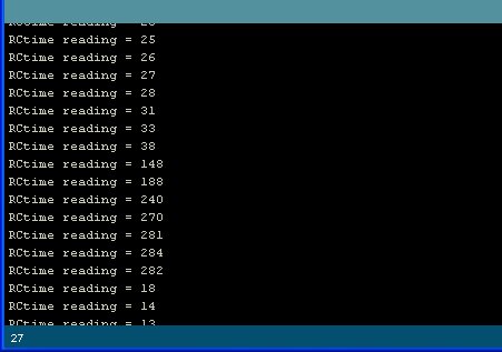
    Serial.print("RCtime reading = ");
    Serial.println(photocellReading);     // the raw analog reading

    // The brighter it is, the faster it blinks!
    digitalWrite(ledPin, HIGH);
    delay(photocellReading);
    digitalWrite(ledPin, LOW);
    delay(photocellReading);
  }
  delay(100);
}

// Uses a digital pin to measure a resistor (like an FSR or photocell!)
// We do this by having the resistor feed current into a capacitor and
// counting how long it takes to get to Vcc/2 (for most arduinos, thats 2.5V)
int RCtime(int RCpin) {
  int reading = 0;  // start with 0

  // set the pin to an output and pull to LOW (ground)
  pinMode(RCpin, OUTPUT);
  digitalWrite(RCpin, LOW);

  // Now set the pin to an input and...
  pinMode(RCpin, INPUT);
  while (digitalRead(RCpin) == LOW) { // count how long it takes to rise up to HIGH
    reading++;      // increment to keep track of time

    if (reading == 30000) {
      // if we got this far, the resistance is so high
      // its likely that nothing is connected!
      break;           // leave the loop
    }
  }
  // OK either we maxed out at 30000 or hopefully got a reading, return the count

  return reading;
}
Source: cds
Traduit avec l'autorisation d'AdaFruit Industries - Translated with the permission from Adafruit Industries - www.adafruit.com
Toute référence, mention ou extrait de cette traduction doit être explicitement accompagné du texte suivant : « Traduction par MCHobby (www.MCHobby.be) - Vente de kit et composants » avec un lien vers la source (donc cette page) et ce quelque soit le média utilisé.
L'utilisation commercial de la traduction (texte) et/ou réalisation, même partielle, pourrait être soumis à redevance. Dans tous les cas de figures, vous devez également obtenir l'accord du(des) détenteur initial des droits. Celui de MC Hobby s'arrêtant au travail de traduction proprement dit.
