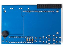
RASP-LCD-RGB-Assembler
|
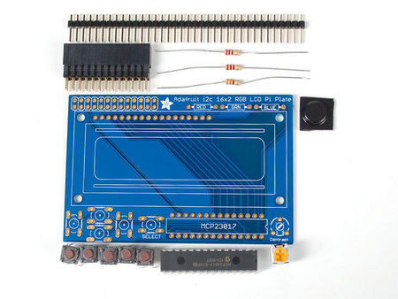
Vérifiez que le kit contient bien tous les éléments nécessaires.
|
|
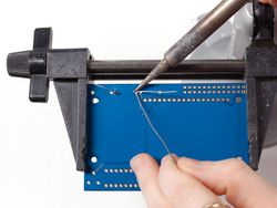
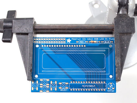
Placez le circuit imprimé sur votre étau 3ieme main (ou équivalent), chauffez votre fer à souder et assurez vous que vous êtes fin prêt à vous lancer! Nous allons commencer avec la première résistance de l'emplacement GREEN (vert) - qui est codifié est les bandes de Courbez les pattes de la résistance en forme d'agrafe et glissez la dans les trous marqués GREEN sur la carte. Les résistance n'ont pas de sens de raccordement (non directionnelle)... vous pouvez donc les placer dans un sens ou dans l'autre, ce sera parfait. |
|
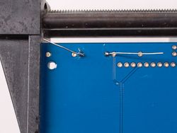
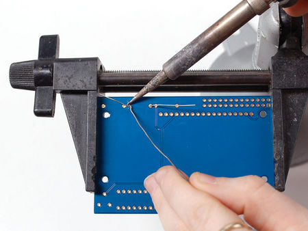
Tordez les pattes de la résistance de l'autre côté du PCB pour qu'elle reste bien en place à plat contre la carte. Retournez ensuite la carte.
De cette façon, la résistance ne tombe pas pendant que vous la soudez. Soudez les deux pattes de la résistance avec votre fer à souder bien chaud. Pour ce faire, chauffez la pastille et la patte en même temps pendant 2 à 3 secondes. Ensuite, faites fondre un bout de fil à souder sur la jointure chauffée en laissant votre fer bien en place... retirez votre fil a souder puis votre fer. |
|
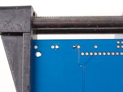
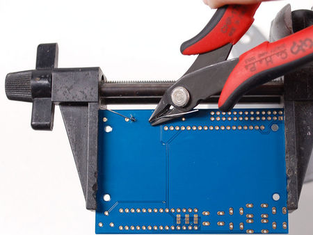
Une fois la soudure terminée, vous pouvez couper les pattes de la résistance (la partie excédentaire). Cela evite d'avoir des court-circuits :-) . Utilisez une pince coupante ou pince coupante (diagonale) pour raccourcir les fils juste au dessus du joint de soudure. |
|
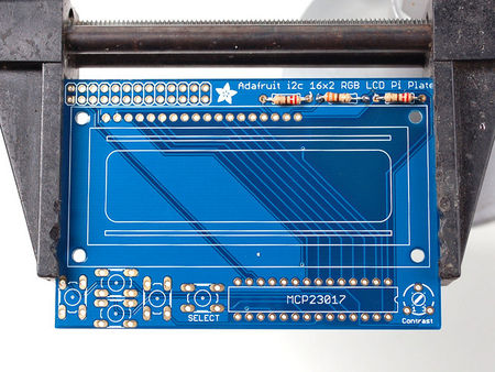
Puisque vous vous en êtes si bien sorti avec la première résistance, nous allons maintenant placer toutes les autres..
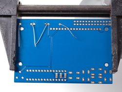
Les deux résistances de 220 ohms à placer sur les emplacements RED (rouge) and BLUE (bleu) - nommés ainsi parce qu'il s'agit des résistances séries pour rétro-éclairage RGB de l'écran LCD. Ces résistances disposent du code couleur Rouge Rouge Brun Or. |
|
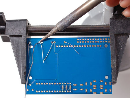
Soudez les résistances comme nous l'avons fait pour la première. |
|
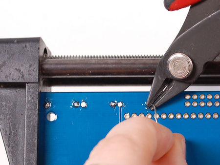
Coupez ensuite toutes les pattes. |
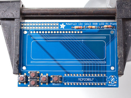
|
Ensuite, nous allons placer les boutons.
Ces boutons sont utiles pour envoyer un signal au Pi (pour, par exemple, créer un système de menu rudimentaire). Nous avons un petit pavé directionnel (4 directions) pour les entrées haut/bas/gauche/droite (respectivement up/down/left/right en anglais) et un bouton additionnel sur la droite pour activer la sélection (nommé SELECT en anglais). Ces 5 boutons devrait vous permettre de 'communiquer' facilement avec votre avec vos projets. Ils sont connectés par le bus I2C sur le circuit intégré d'extension (I2C port expander)... ces boutons ne nécessitent donc pas l'usage de broches supplémentaires sur le Pi. La librairie fait tout le necessaire pour savoir s'ils ont étés pressés. Tous les boutons sont identiques, ils devraient prendre place facilement. Poussez un peu sur chaque bouton jusqu'à ce qu'il s'enfonce bien en place à plat sur la carte. Le kit à récemment été modifié pour placer les boutons à DROITE plutôt qu'à gauche. Les boutons se placent de la même façon sauf que c'est à droite |
|
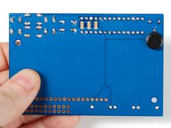
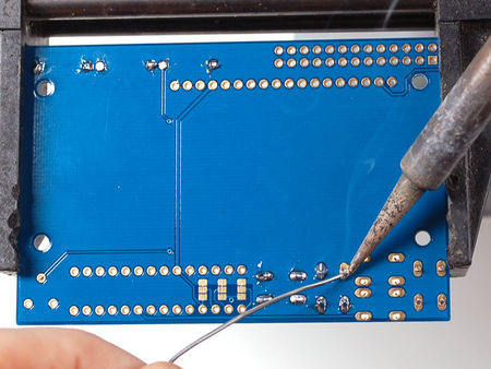
Flip over the PCB and check that all the legs for the buttons are sticking out.
Solder each leg, taking care not to accidentally 'short' two button legs together. The ones for the directional pads are very close! |
|
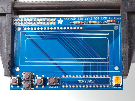
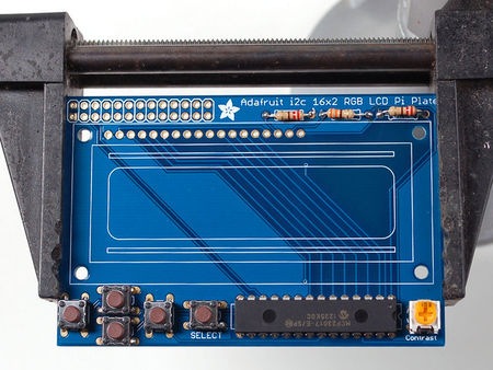
Next, place the 10K potentiometer (the orange-faced thing with three legs) into the spot above the RESET button. It will only fit one way. This is the contrast potentiometer which will adjust how dark the characters appear. All displays are slightly different so you'll adjust this once the display is soldered in.
The kit may come with two potentiometers - a big blue one for breadboarding the LCD and a smaller orange one for the shield kit. You can throw away or recycle the blue one, use only the orange one here! We recently adjusted the kit to have the potentiometer in the center rather than the right, goes in the same way, just in the middle! |
|
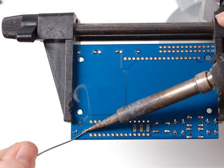
Flip over the PCB and solder in the three legs of the potentiometer
|
|
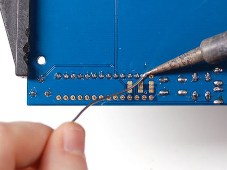
We're nearly done! Now we will place the I2C port expander chip. Double check that it has the MCP23017-E/SP marking on it. This is a 16-pin expander chip, that uses the i2c bus. That means you can send it commands using the i2c pins on an Pi and control 16 more digital pins! 5 of those pins go to the buttons, 6 go to the LCD control and 3 are used for the backlight (the remaining 2 are unused).
Unlike buttons or resistors, chips do have a direction and the must be put in the right way! First, use a flat table to carefully bend the legs of the chip so they are parallel. Then slip it into the silkscreened outline so that the notch at the end of the chip is on the right. Click the image to the left to make absolutely sure you've got it in the right way. Once you are sure, press the chip into place We recently adjusted the kit so the chip is more to the left, its the same alignment, just shifted over |
|
Flip over the PCB and solder in the 28 pins of the port expander.
|
|
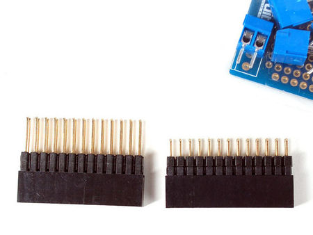
Next we will attach the header, there is a standard 'extra tall' header included in the kit. However, if you want to attach a cobbler or GertBoard, etc to the plate, you may want to opt for one of our stacking headers, they're extra long so you can plug in an IDC cable on top! |
|
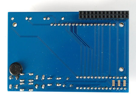
Before we solder in the header, remove the bumper from the backing and attach it on the underneath so its right over the Ethernet jack when the PCB is plugged in.
On kits where the buttons are on the left, put it right below the contrast pot, as shown. This will keep the pot from touching the Ethernet jack. On kits where the buttons are on the right, put it right next to the buttons (it shouldnt overlap any button legs) sitting flat |
|
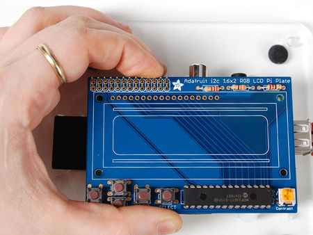
Place the 2x13 header onto your Pi, and slide the plate on top, it should fit perfectly. |
|
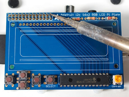
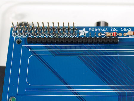
Now we will solder all 26 pins for the plate - this will send power and data between the two boards and also provide a mechanical stability. You may need to hold the plate down with tape to get it sitting flat against the Pi.
Solder in one pin, we suggest the top right, then check if the plate is sitting flat. If not, heat up the joint with one hand while stabilizing with the other until its right. Then solder the other 25 pins |
|
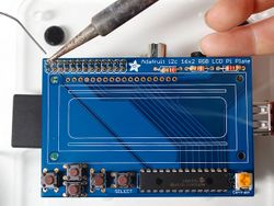
Finally, we place the LCD.
Break off a piece of 18 or 16 pin header from the stick in the kit. If you have an RGB display, you'll need 18, for a blue&white you'll need 16 Place the header into the remaining slot with the long ends of the pins sticking UP. If you have only 16 pins, leave the two rightmost pads empty |
|
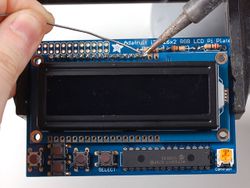
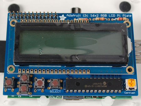
Slide the LCD over the header so that it is perfectly centered over the four holes and the silkscreen.
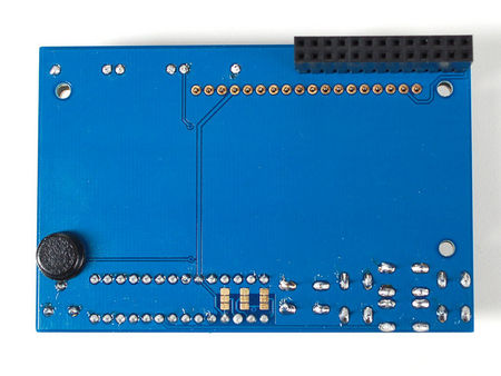
The LCD should 'snap' in against the buttons Solder all the pins! |
|
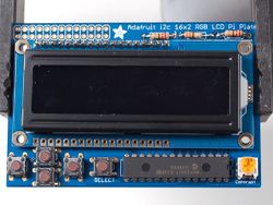
Flip over the assembly, carefully. Then solder in the 16 or 18 pins of header |
|
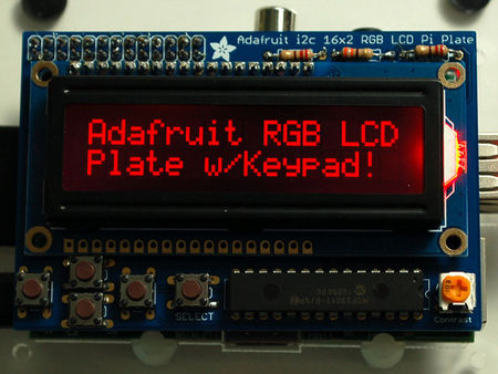
That's it! You're done soldering, now you just have to run the code in the Usage section next. |
Source: Adafruit 16x2 Character LCD + Keypad for Raspberry Pi écrit par LadyAda pour AdaFruit. Crédit AdaFruit Industries
Réalisé avec l'aide de Mr Carette J. à qui nous remettons tous nos remerciements.
Toute référence, mention ou extrait de cette traduction doit être explicitement accompagné du texte suivant : « Traduction par MCHobby (www.MCHobby.be) - Vente de kit et composants » avec un lien vers la source (donc cette page) et ce quelque soit le média utilisé.
L'utilisation commercial de la traduction (texte) et/ou réalisation, même partielle, pourrait être soumis à redevance. Dans tous les cas de figures, vous devez également obtenir l'accord du(des) détenteur initial des droits. Celui de MC Hobby s'arrêtant au travail de traduction proprement dit.
Traduit avec l'autorisation d'AdaFruit Industries - Translated with the permission from Adafruit Industries - www.adafruit.com
