Senseur Thermocouple-Utiliser
AD595
If you're using an AD595 interface chip, you can simply connect the voltage output to an analog input on your microcontroller and do some basic math to multiply the 10 mV/°C input into numerical output.
MAX6675/MAX31855
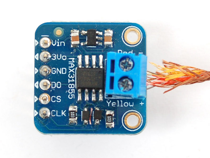
If you're planning to use the MAX6675/MAX31855, there's a little more work to be done. First off, Vin and GND must connect to a 3-5V supply. Then the three data pins must connect to digital IO pins:
- CLK (clock) is an input to the MAX6675/MAX31855 (output from microcontroller) which indicates when to present another bit of data
- DO (data out) is an output from the MAX6675/MAX31855 (input to the microcontroller) which carries each bit of data
- CS (chip select) is an input to the MAX6675/MAX31855 (output from the microcontroller) which tells the chip when its time to read the thermocouple and output more data.
In the beginning of our sketches, we define these pins. For our examples DO connects to digital 3, CS connects to digital 4, and CLK connects to pin 5
Using a Thermocouple Created by Ladyada
If you're using an AD595 interface chip, you can simply connect the voltage output to an analog input on your microcontroller and do some basic math to multiply the 10 mV/°C input into numerical output.
attached.jpg
If you're planning to use the MAX6675/MAX31855, there's a little more work to be done. First off, Vin and GND must connect to a 3-5V supply. Then the three data pins must connect to digital IO pins:
   CLK (clock) is an input to the MAX6675/MAX31855 (output from microcontroller) which indicates when to present another bit of data
   DO (data out) is an output from the MAX6675/MAX31855 (input to the microcontroller) which carries each bit of data
   CS (chip select) is an input to the MAX6675/MAX31855 (output from the microcontroller) which tells the chip when its time to read the thermocouple and output more data.
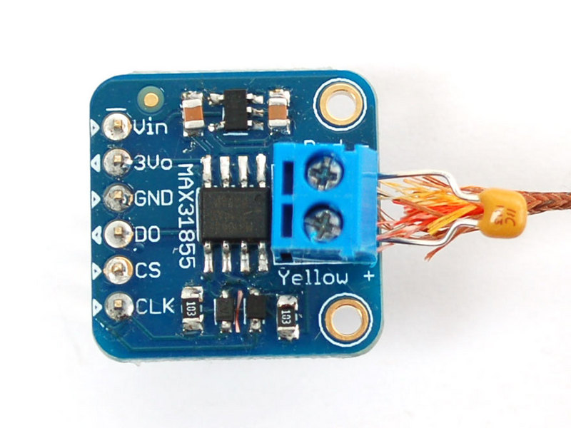
In the beginning of our sketches, we define these pins. For our examples DO connects to digital 3, CS connects to digital 4, and CLK connects to pin 5 cap.jpg If you are using the MAX31855 v1.0 in a noisy environment, you may need to add a 0.01uF capacitor across the thermocouple leads.
The MAX31855 does not support grounded thermocouples - if the sensor touches ground the chip will return an error
Librairie Arduino
If you have an older MAX6675 breakout, download the MAX6675 Arduino library code by going to the github page and clicking Download Source. Then uncompress the folder and rename it MAX6675 and install it into the library folder according to our handy tutorial.
If you have the newer MAX31855 breakout, download the MAX31855 Arduino library code by going to the github page and clicking Download Source. Then uncompress the folder and rename it Adafruit_MAX31855 and install it into the library folder according to our handy tutorial.
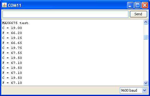
Restart the Arduino IDE and open up the File->Examples->MAX6675/Adafruit_MAX31855->serialthermocouple sketch and upload it to your Arduino. Once uploaded, open up the serial port monitor to display the current temperatures in both Celsius and Fahrenheit
As you can see, its pretty simple to use the library, simply tell the sensor object what the clock, chip select and data pins are, then call readCelsius() or readFahrenheit() to get a floating point result.
Ajouter un afficheur
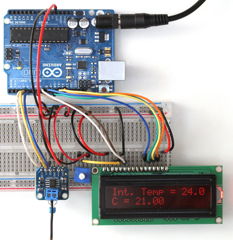
A common request is to have the temperature output onto a 'classic' character LCD such as the ones in this tutorial.
For this wiring, we connected CLK to digital 3, CS to digital 4 and DO to digital 5. Once you get it working, you can change the pin connections in the sketch
We have an example sketch for this as well. First get the ***LINK*** LCD working by following our tutorial ***. Now load up the new sketch File->Examples->MAX31855>lcdthermocouple and plug in the thermocouple module as we did in the serial thermocouple test, you'll see the internal temperature and the thermocouple temperature displayed in Celsius
Source: Thermocouple
Tutoriel créé par LadyAda pour AdaFruit Industries.
Traduit par Meurisse D. pour MCHobby.be
Traduit avec l'autorisation d'AdaFruit Industries - Translated with the permission from Adafruit Industries - www.adafruit.com
Toute référence, mention ou extrait de cette traduction doit être explicitement accompagné du texte suivant : « Traduction par MCHobby (www.MCHobby.be) - Vente de kit et composants » avec un lien vers la source (donc cette page) et ce quelque soit le média utilisé.
L'utilisation commercial de la traduction (texte) et/ou réalisation, même partielle, pourrait être soumis à redevance. Dans tous les cas de figures, vous devez également obtenir l'accord du(des) détenteur initial des droits. Celui de MC Hobby s'arrêtant au travail de traduction proprement dit.


