Différences entre versions de « ADF-LED-BACKPACK-8x8-Bicolor »
| Ligne 8 : | Ligne 8 : | ||
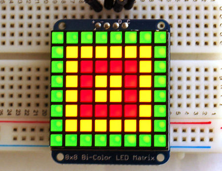
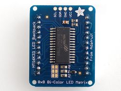
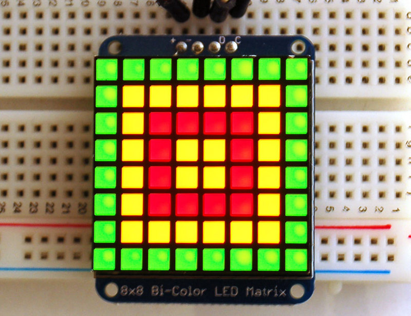
|text= This version of the LED backpack is designed for these bright and colorful square=pixeled 8x8 matrices. They have 64 red and 64 green LEDs inside, for a total of 128 LEDs controlled as a 8x16 matrix. This backpack solves the annoyance of using 24 pins or a bunch of chips by having an I2C constant-current matrix controller sit neatly on the back of the PCB. The controller chip takes care of everything, drawing all 128 LEDs in the background. All you have to do is write data to it using the 2-pin I2C interface. There are three address select pins so you can select one of 8 addresses to control up to 8 of these on a single 2-pin I2C bus (as well as whatever other I2C chips or sensors you like). The driver chip can 'dim' the entire display from 1/16 brightness up to full brightness in 1/16th steps. It cannot dim individual LEDs, only the entire display at once. }} | |text= This version of the LED backpack is designed for these bright and colorful square=pixeled 8x8 matrices. They have 64 red and 64 green LEDs inside, for a total of 128 LEDs controlled as a 8x16 matrix. This backpack solves the annoyance of using 24 pins or a bunch of chips by having an I2C constant-current matrix controller sit neatly on the back of the PCB. The controller chip takes care of everything, drawing all 128 LEDs in the background. All you have to do is write data to it using the 2-pin I2C interface. There are three address select pins so you can select one of 8 addresses to control up to 8 of these on a single 2-pin I2C bus (as well as whatever other I2C chips or sensors you like). The driver chip can 'dim' the entire display from 1/16 brightness up to full brightness in 1/16th steps. It cannot dim individual LEDs, only the entire display at once. }} | ||
| − | [[Fichier:ADF-LED-BACKPACK-MATRICE-BI-01.jpg]] | + | [[Fichier:ADF-LED-BACKPACK-MATRICE-BI-01.jpg|450px]] |
{{Ambox | {{Ambox | ||
Version du 3 février 2013 à 20:59
Bi-Color 8x8 Matrix
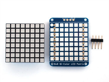
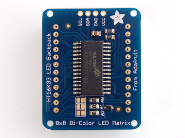
This version of the LED backpack is designed for these bright and colorful square=pixeled 8x8 matrices. They have 64 red and 64 green LEDs inside, for a total of 128 LEDs controlled as a 8x16 matrix. This backpack solves the annoyance of using 24 pins or a bunch of chips by having an I2C constant-current matrix controller sit neatly on the back of the PCB. The controller chip takes care of everything, drawing all 128 LEDs in the background. All you have to do is write data to it using the 2-pin I2C interface. There are three address select pins so you can select one of 8 addresses to control up to 8 of these on a single 2-pin I2C bus (as well as whatever other I2C chips or sensors you like). The driver chip can 'dim' the entire display from 1/16 brightness up to full brightness in 1/16th steps. It cannot dim individual LEDs, only the entire display at once.
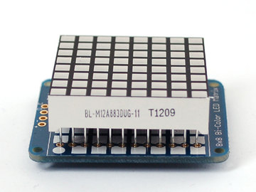
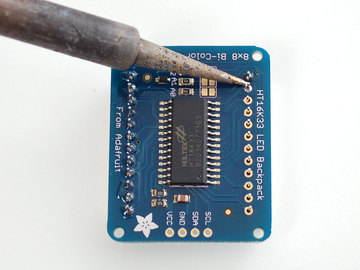
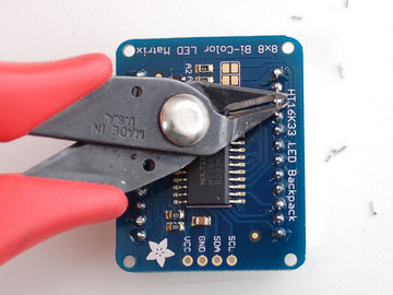
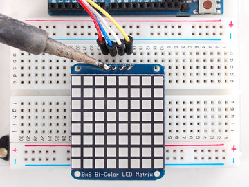
| Pay close attention to the instructions for positioning the matrix. It must be oriented correctly to work and is almost impossible to remove it once it has been soldered to the backpack! |
Bi-Color 8x8 LED Backpack Firmware
We wrote a basic library to help you work with the bi-color 8x8 matrix backpack. The library is written for the Arduino and will work with any Arduino as it just uses the I2C pins. The code is very portable and can be easily adapted to any I2C-capable micro.
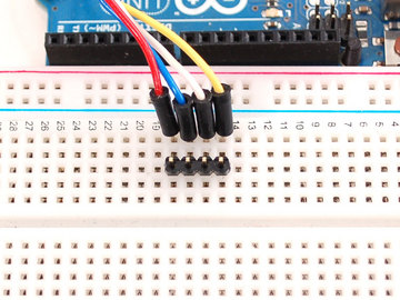
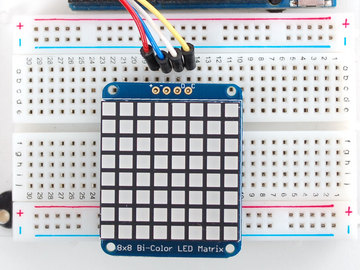
Wiring to the matrix is really easy
- Connect CLK to the I2C clock - on Arduino UNO thats Analog #5, on the Leonardo its Digital #3, on the Mega its digital #21
- Connect DAT to the I2C data - on Arduino UNO thats Analog #4, on the Leonardo its Digital #2, on the Mega its digital #20
- Connect GND to common ground
- Connect VCC+ to power - 5V is best but 3V also seems to work for 3V microcontrollers.
Next, download the Adafruit LED Backpack library from github . To download click the DOWNLOADS button in the top right corner, rename the uncompressed folder Adafruit_LEDBackpack. Check that the Adafruit_LEDBackpack folder contains Adafruit_LEDBackpack.cpp and Adafruit_LEDBackpack.h Place the Adafruit_LEDBackpack library folder your arduinosketchfolder/libraries/ folder. You may need to create the libraries subfolder if its your first library. You'll also need to download the Adafruit GFX library that provides the graphics drawing routines. Restart the IDE.
Once you've restarted you should be able to select the File->Examples->Adafruit_LEDBackpack->bicolor88 example sketch. Upload it to your Arduino as usual. You should see a basic test program that goes through a bunch of different drawing routines
Once you're happy that the matrix works, you can write your own sketches. The 8x8 matrix supports everything the Adafruit GFX library - drawing pixels, lines, rectangles, circles, triangles, roundrects, and small bitmaps. For more details [Tutoriel Librairie Adafruit GFX check out the GFX page which will detail all of the GFX routines].
All the drawing routines only change the display memory kept by the Arduino. Don't forget to call writeDisplay() after drawing to 'save' the memory out to the matrix via I2C.
There are also a few small routines that are special to the matrix:
- setBrightness(brightness) - will let you change the overall brightness of the entire display. 0 is least bright, 15 is brightest and is what is initialized by the display when you start
- blinkRate(rate) - You can blink the entire display. 0 is no blinking. 1, 2 or 3 is for display blinking.
Source: Control small led matrice with ease créé par LadyAda pour AdaFruit Industries. Crédit AdaFruit Industries
Traduit avec l'autorisation d'AdaFruit Industries - Translated with the permission from Adafruit Industries - www.adafruit.com
Toute référence, mention ou extrait de cette traduction doit être explicitement accompagné du texte suivant : « Traduction par MCHobby (www.MCHobby.be) - Vente de kit et composants » avec un lien vers la source (donc cette page) et ce quelque soit le média utilisé.
L'utilisation commercial de la traduction (texte) et/ou réalisation, même partielle, pourrait être soumis à redevance. Dans tous les cas de figures, vous devez également obtenir l'accord du(des) détenteur initial des droits. Celui de MC Hobby s'arrêtant au travail de traduction proprement dit.

