Différences entre versions de « Rasp-PiGRRL-2-Alimentation »
| Ligne 23 : | Ligne 23 : | ||
{{asm-row|img=Rasp-PiGRRL-2-Alimentation-05.jpg}} | {{asm-row|img=Rasp-PiGRRL-2-Alimentation-05.jpg}} | ||
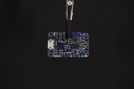
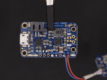
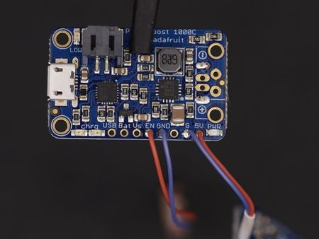
| − | {{asm-text}} | + | {{asm-text}} Glissez un morceau de gaine thermo-rétractable sur les fils connectés aux broches '''Vin''' et '''Gnd'''. Ensuite, placez votre PowerBoost 1000C dans l'étau 3ième main. |
| − | Glissez un morceau de gaine thermo-rétractable sur les fils connectés aux broches '''Vin''' et '''Gnd'''. Ensuite, placez votre PowerBoost 1000C dans l'étau 3ième main. | ||
Soudez: | Soudez: | ||
* le fil '''VIN''' de l'ampli sur la broche '''5V''' du PowerBoost. | * le fil '''VIN''' de l'ampli sur la broche '''5V''' du PowerBoost. | ||
* Le fil '''Gnd''' de l'ampli sur la broche '''G ''' du PowerBoost 1000C. | * Le fil '''Gnd''' de l'ampli sur la broche '''G ''' du PowerBoost 1000C. | ||
| + | |||
| + | {{asm-row|img=Rasp-PiGRRL-2-Alimentation-06.jpg|640px}} | ||
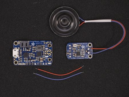
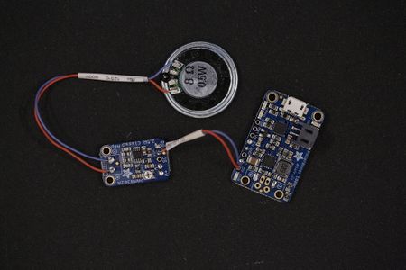
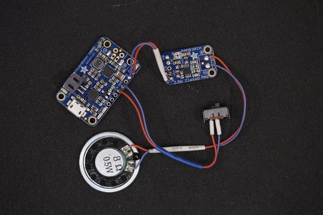
| + | {{asm-text}} Voilà! Maintenant notre amplificateur et haut-parleurs sont tous deux branchés sur le PowerBoost 1000C. | ||
{{asm-end}} | {{asm-end}} | ||
| − | == | + | == Couper l'alimentation == |
| − | |||
| − | |||
| − | |||
{{asm-begin}} | {{asm-begin}} | ||
| Ligne 43 : | Ligne 42 : | ||
{{asm-img|img=Rasp-PiGRRL-2-Alimentation-10.jpg}} | {{asm-img|img=Rasp-PiGRRL-2-Alimentation-10.jpg}} | ||
{{asm-img|img=Rasp-PiGRRL-2-Alimentation-11.jpg}} | {{asm-img|img=Rasp-PiGRRL-2-Alimentation-11.jpg}} | ||
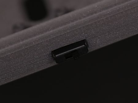
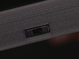
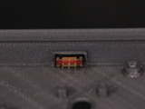
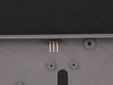
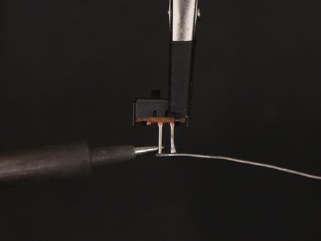
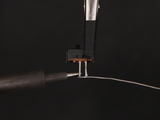
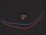
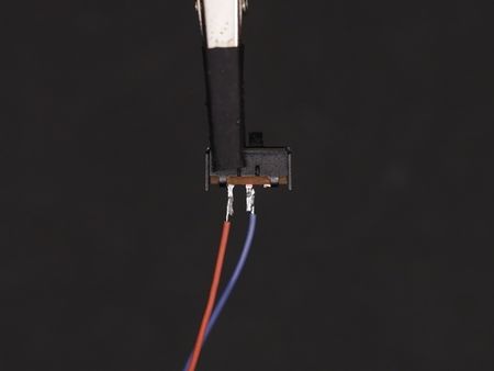
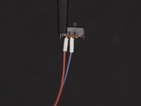
| − | {{asm-text}} | + | {{asm-text}} Nous allons maintenant connecter notre interrupteur Breadboard sur le PowerBoost 1000C. |
| − | + | ||
| + | Commençons par vérifier que l'interrupteur prend correctement place dans l'ouverture prévue dans le boîtier. | ||
| + | |||
| + | Insérez l'interrupteur dans l'orifice prévu dans la boîtier du bas. Press it all the way through. If it's too tight, you can use a filing tool to open it up. | ||
{{asm-row|img=Rasp-PiGRRL-2-Alimentation-12.jpg}} | {{asm-row|img=Rasp-PiGRRL-2-Alimentation-12.jpg}} | ||
Version du 6 mars 2018 à 12:07
Préparer le PowerBoost 1000C
Couper l'alimentation
Crédit: AdaFruit Industries www.adafruit.com
<a href="#wired-power-circuit" class="anchor-link"></a>Wired Power Circuit
Now we have our amp, speaker, PowerBoost and slide switch all wired up and connected. Now's a good time to take a break or continue!
Source: PiGRRL 2 - Make a portable Raspberry Pi 2 game console
Créé par les frères Ruiz pour AdaFruit Industries.
Traduction réalisée par Wrotny A pour MCHobby.be.
Toute référence, mention ou extrait de cette traduction doit être explicitement accompagné du texte suivant : « Traduction par MCHobby (www.MCHobby.be) - Vente de kit et composants » avec un lien vers la source (donc cette page) et ce quelque soit le média utilisé.
L'utilisation commercial de la traduction (texte) et/ou réalisation, même partielle, pourrait être soumis à redevance. Dans tous les cas de figures, vous devez également obtenir l'accord du(des) détenteur initial des droits. Celui de MC Hobby s'arrêtant au travail de traduction proprement dit.
Traduit avec l'autorisation d'AdaFruit Industries - Translated with the permission from Adafruit Industries - www.adafruit.com

