Différences entre versions de « ADAFRUIT-FONA-Pinout »
| Ligne 28 : | Ligne 28 : | ||
== Connecteur SIM (à l'arrière) == | == Connecteur SIM (à l'arrière) == | ||
| + | {{traduction}} | ||
A 2G Mini SIM card is required to use the module. Nearly any cell phone shop can sell you a SIM card. It must be a 2G GSM card. AT&T in the US does not sell these anymore! They are shutting down their GSM network, and only T-mobile sells and supports a GSM network. If you are in another country, chances are you can just ask for a GSM 2G card. | A 2G Mini SIM card is required to use the module. Nearly any cell phone shop can sell you a SIM card. It must be a 2G GSM card. AT&T in the US does not sell these anymore! They are shutting down their GSM network, and only T-mobile sells and supports a GSM network. If you are in another country, chances are you can just ask for a GSM 2G card. | ||
Version du 7 novembre 2015 à 10:26
|
|
En cours de traduction/élaboration. |
Vue d'ensemble
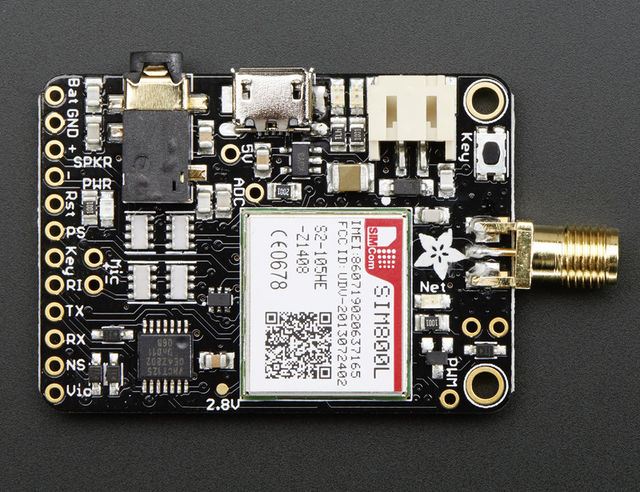
Il y a beaucoup de composants assemblés sur la mini carte GSM Fona, Faisons un petit tour de toutes les broches, boutons et indicateurs et apprendre ce qu'ils font.

Crédit: AdaFruit Industries www.adafruit.com
Les connecteurs
Il y a trois connecteurs externe sur le côté gauche de la carte. Du haut en bas, nous avons un connecteur mini-JST 2 pôles, un connecteur microUSB et connecteur casque.
- JST 2-broches - ce connecteur vous permet de brancher un accu. Il fonctionne avec nos accus Lipoly mais étant donné que le courant de charge est de 500mA (et que le module peut générer d'importante pointes d'appel de courant), nous recommande d'utiliser des accu de 500mAh ou 1200mAh. Vous pouvez également connecter un câble JST sur ce connecteur si vous avez d'autres plans.
- Connecteur MicroUSB - C'est le port permettant de recharger l'accu LiPoly/LiIon. Le SIM800 dispose d'une interface USB mais c'est UNIQUEMENT pour reprogrammer le module avec un environnement de programmation (non disponible et vraiment couteux). Par consquent, il est uniquement destiné à recharger l'accu Lipoly. Le courant de charge est de 500mA max.
- Connecteur casque - dit headphone jack, il s'agit d'un connecteur 'standard' TRRS de 3.5mm (4 poles) avec casque stéréo et microphone mono. N'import quel casque compatible 'iPhone' ou 'Android' devrait fonctionner (mais pas le casque original iPhone!). Adafruit à essayé une dizaine de module, d'une façon générale, plus il est coûteux et meilleur est le rendu sonore (ainsi que le comfort) mais pour une raison inconnue, le micro du casque iPhone officiel ne fonctionne pas.
La base est Mic+, le premier anneau la masse/GND, le second anneau et la pointe sont utilisés pour le signal audio stéréo.
Comme le module ne dispose pas de sortie stéréo, les deux signaux stéréo sont reliés ensembles.

Crédit: AdaFruit Industries www.adafruit.com
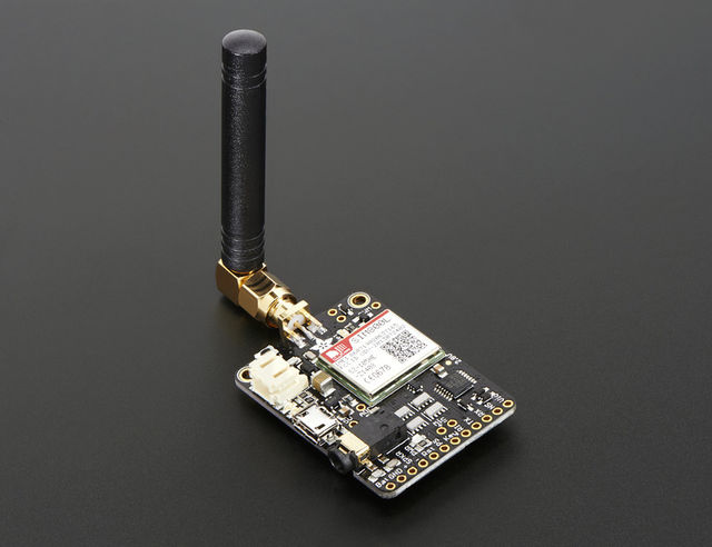
Connecteur d'Antenne
Vous pouvez brancher l'antenne sur le dessus de la carte (soit sur le connecteur SMA comme sur l'image, soit sur le connecteur µFL suivant la version de votre Fona).
Une antenne est nécessaire pour utiliser ce module pour n'importe quel type de communication (voie, donnée, SMS, même pour intérroger la carte SIM!).
Il existe deux version du Fona: le Fona SMA et le Fona µFL. Vous pouvez soit utiliser une µFL antenne GSM de type sticker, ou utiliser un adaptateur µFL vers SMA et ensuite utiliser une Antenne SMA GSM standard
Si vous disposez de la version SMA, vous pouvez connecter directement une SMA antenna. Nous recommandons l'usage d'une antenne GSM/GPRS Quad band, mais vous pouvez également utiliser une antenne simple ou double bande si vous êtes certains de la gamme de fréquence disponibles dans votre région (assurez-vous d'avoir l'antenne qui corresponde à la gamme de fréquence en vigueur).

Crédit: AdaFruit Industries www.adafruit.com
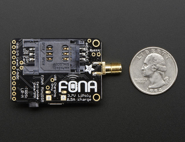
Connecteur SIM (à l'arrière)
|
|
En cours de traduction/élaboration. |
A 2G Mini SIM card is required to use the module. Nearly any cell phone shop can sell you a SIM card. It must be a 2G GSM card. AT&T in the US does not sell these anymore! They are shutting down their GSM network, and only T-mobile sells and supports a GSM network. If you are in another country, chances are you can just ask for a GSM 2G card.
MicroSIMs won't fit - so make sure its a "Mini" SIM. Mini SIMs are 1" x 0.6" / 25mm x 15mm. These are by far the most common size.
Most cards come with a voice and/or data plan. If you want to make phone calls and SMS's you'll need a voice plan. If you want to transmit data like fetching a webpage, you'll need a data plan.
Les breakouts (en bas)
The most important pins are broken out at the bottom of the board. Not all of these are required, but they are all hella useful
These are in rough order of most important (not in linear order like we usually do)
These pins are all 3-5V input safe and if they are an output, the logic level is whatever Vio is set to.
- Vio - THIS IS THE MOST IMPORTANT PIN! This is the pin that you MUST drive with an external voltage from 3V-5V to set the logic level converter. The converter also buffers the indicator LEDs so NOTHING will appear to work unless this pin is powered! You should set the voltage to whatever voltage your microcontroller uses for logic. A 5V micro (like Arduino) should have it be 5V, a 3V logic micro should set it to 3V.
- Key - This is also a super important pin (but not as important as Vio). This is the power on/off indicator. Its also tied to the button in the top left. Tie this pin to ground for 2 seconds to turn the module on or off. It's not a level signal so it isn't like "low is off, high is on" - instead you must pulse it for 2 seconds to turn off/on. The module comes by default off. Tie this permanently to ground if you never want your micro to turn off the FONA for power saving
- PS - Cette broche correspond à la LED Power Status qui indique si le module est alimenté. *** It is low when the module is off and high when the module has power. If you're using the Key button or pin, you can monitor this pad to see when the module's booted up. This is tied to the LED Pwr aussi.
- NS - c'est la broche Network Status (Status réseau). It pulses to signal the current status of the module. This is also tied to the Net LED so for more detail see the LEDs section below.
- Reset - this is module hard reset pin. By default it has a high pull-up (module not in reset). If you absolutely got the module in a bad space, toggle this pin low for 100ms to perform a hard reset.
- RX & TX - OK now that I made you read all that you can actually use the UART pins. The module uses UART to send and receive commands and data. These pins are auto-baud so whatever baud rate you send "AT" after reset or boot is the baud rate is used. le signal RX rentre dans le module, tandis que le signal TX sort du module.
- RI - Il s'agit du signal Ring Indicator (Indicateur de sonnerie). It is basically the 'interrupt' out pin from the module. It is by default high and will pulse low for 120ms when a call is received. It can also be configured to pulse when an SMS is received.
- SPK+ et SPK- : This is for connecting an external 8 ohm speaker, max 1W. You can configure the module to route calls and FM radio to the headset or the external audio. The two pins are differential so they don't have output DC blocking capacitors. You cannot connect this to a stereo, powered speakers or other non-differential amplifier without adding a 100uF+ blocking cap in series to the + pin and then not using the - pin. Instead, your amp should use GND for the - reference
MIC + et -: this is for connecting an external electret microphone, it will bias the mic with 2V. Most electrets will work just fine. No extra circuitry is required for the mic such as a biaser or amplifier, just wire it up directly!
Les LEDs
- PWR - Blue! Lit when the module is booted and running
- NET - Red! You can use this for checking the current state without sending an AT command:
By watching the blinks you can get a visual feedback on whats going on.- 64ms on, 800ms off - the module is running but hasn't made connection to the cellular network yet
- 64ms on, 3 seconds off - the module has made contact with the cellular network and can send/receive voice and SMS
- 64ms on, 300ms off - the GPRS data connection you requested is active
- Charging - état de rechargement de l'accumulateur Lipo.
- Orange! - This is next to the microUSB jack. Indicates the onboard lipo charger is charging
- Vert! - Recharge terminée! This is next to the JST jack. Indicates that the battery charging is done and the battery is full
Autres breakouts
We scattered a few other breakouts around the board.
- Buzzer and PWM (Top right) - These are tied to the PWM output of the module! The PWM capability is quite nice, it can set any frequency and duty cycle. The PWM pin is directly output from the module and is 0-2.8Vpp. The Buzzer output has a NPN drive transistor so it can run a small vibration motor. Bz+ is the VBat voltage, Bz- is toggled on and off to ground.
- ADC (left middle) - the SIM800 has an ADC that can read 0-2.8VDC from this pin, referenced to ground. It also has an internal battery ADC so you can use this for a sensor or something. You can query the voltage from the UART. 2.8V max, people!
- 5V (left middle) - this is the USB 5V from the microUSB connector when its in and powered. Good if you need to know when the microUSB is plugged in and/or want to recharge the battery from an external plug.
- Point de test 2.8V - We have a test point for the 2.8V internal regulator, its off to the right.
Source: Adafruit FONA - Call phones, send and receive SMSs, & more! All with FONA. Ecrit par Lady Ada pour AdaFruit. Crédit AdaFruit Industries
Traduit par Meurisse D. pour MCHobby.be
Traduit avec l'autorisation d'AdaFruit Industries - Translated with the permission from Adafruit Industries - www.adafruit.com
Toute référence, mention ou extrait de cette traduction doit être explicitement accompagné du texte suivant : « Traduction par MCHobby (www.MCHobby.be) - Vente de kit et composants » avec un lien vers la source (donc cette page) et ce quelque soit le média utilisé.
L'utilisation commercial de la traduction (texte) et/ou réalisation, même partielle, pourrait être soumis à redevance. Dans tous les cas de figures, vous devez également obtenir l'accord du(des) détenteur initial des droits. Celui de MC Hobby s'arrêtant au travail de traduction proprement dit.