AdaFruit Motor Shield Souder
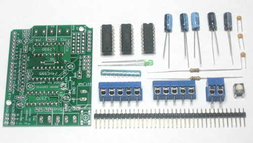
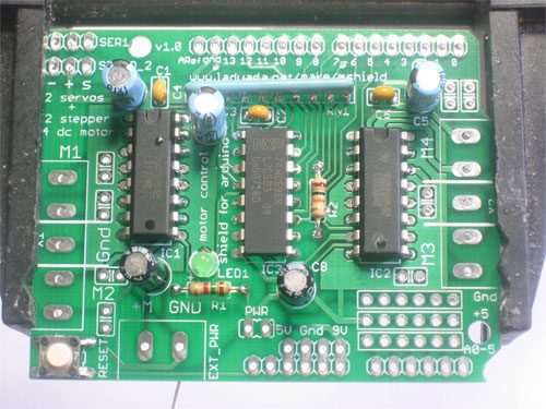
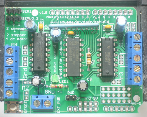
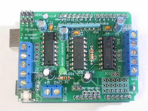
First, check that you have all the parts! Look over the parts list here and shown on the left.
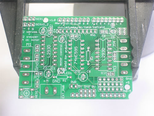
Place the motor shield PCB in a vise or other circuit-board holder and turn on your soldering iron to 700 degrees.
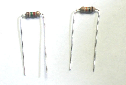
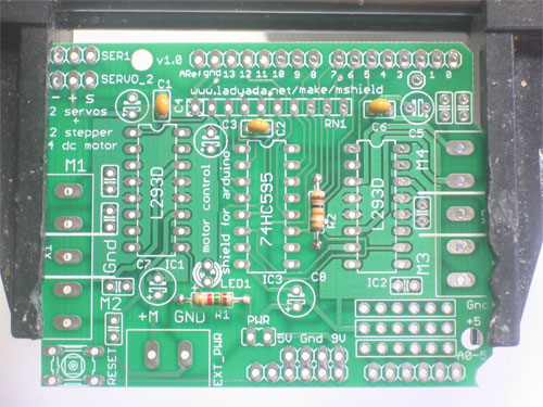
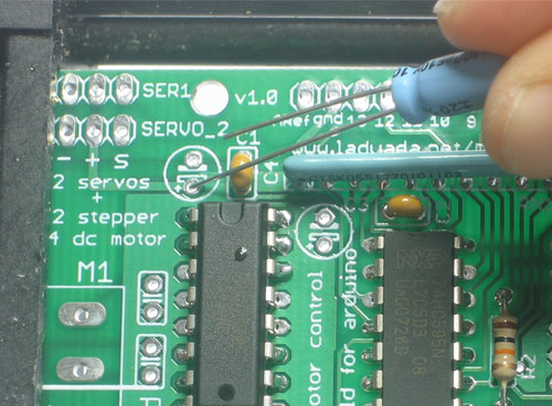
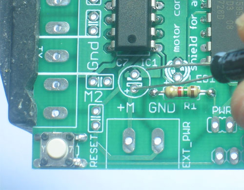
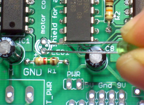
The first parts to go in are the two resistors, R1 (Brown Green Red Gold) and R2 (Brown Black Orange Gold). Bend the resistors so that they look like staples, as seen in this photo
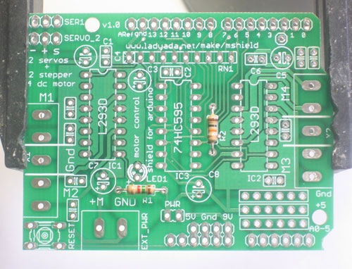
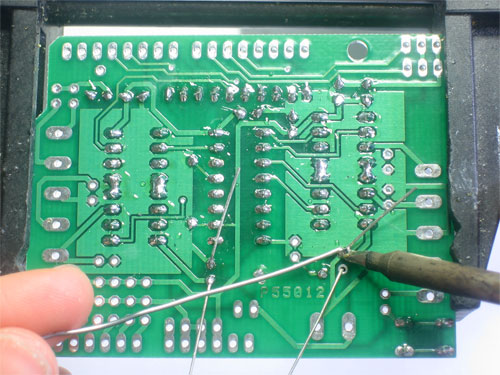
Next, slip the resistors into the PCB as shown, so that they sit flat against the circuit board. Bend the wire legs out a bit so that when the board is flipped over
Resistors are not polarized, that means you can put them in "either way" and they'll work just fine.
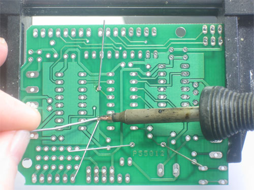
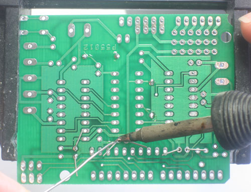
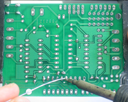
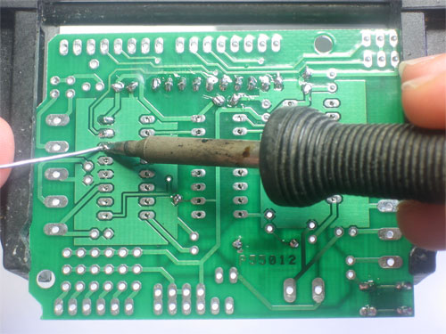
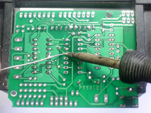
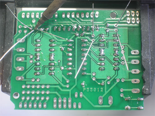
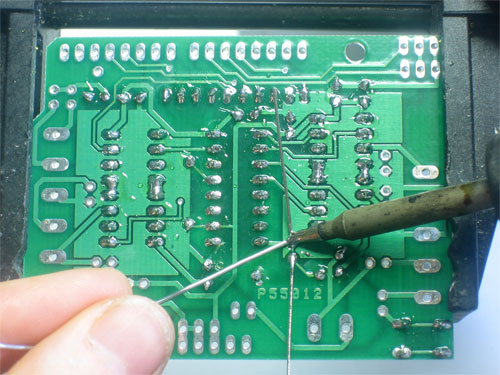
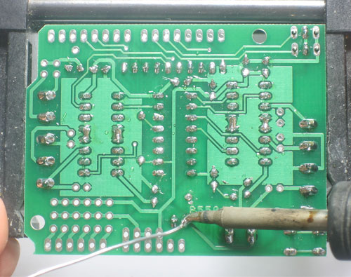
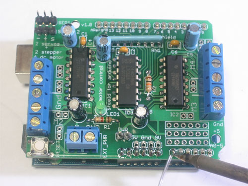
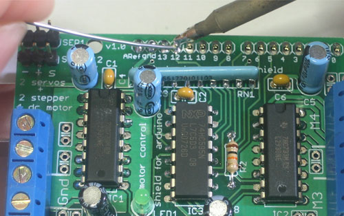
Using your soldering iron tip, heat the resistor wire lead and the metal ring (pad) at the same time, after a few seconds, poke a little solder in so that it melts into a nice cone. Remove the solder and then remove the soldering iron. Do this for all 4 wires.
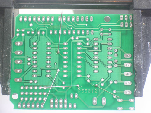
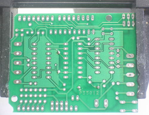
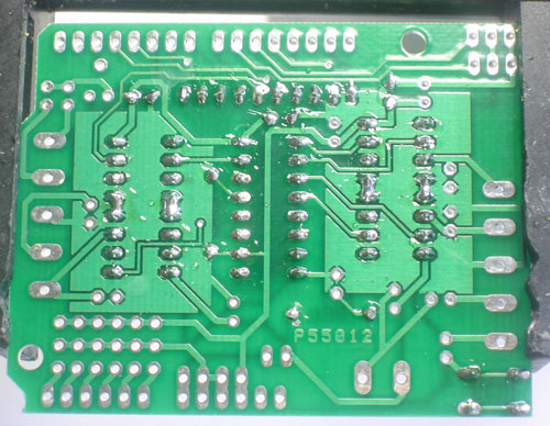
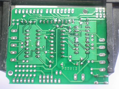
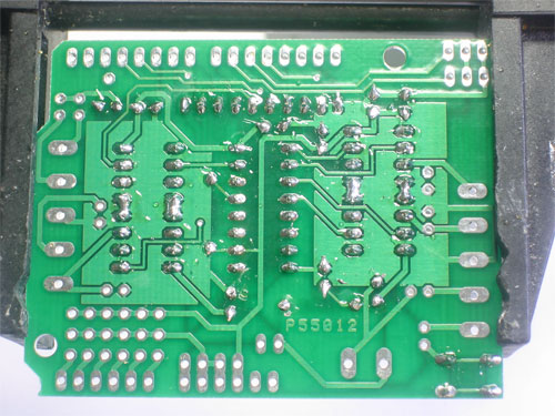
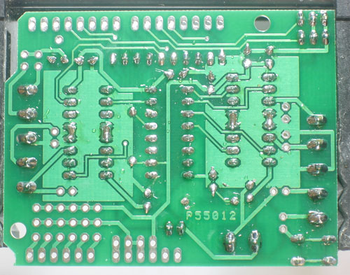
Check your work, you should have clean solder joints
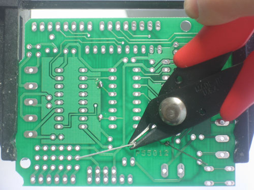
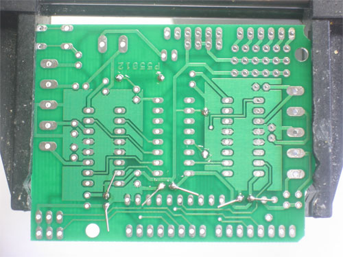
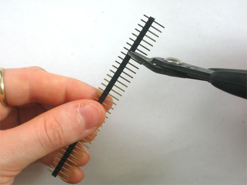
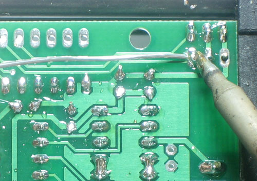
Clip the long leads, just above the solder joint using diagonal cutters
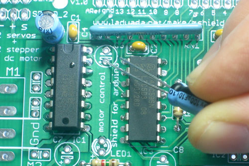
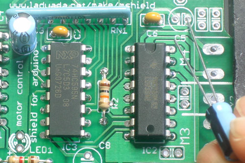
Next place the three yellow ceramic capacitors C4, C2 and C6. Ceramic capacitors are not polarized so you can put them in "either way" and they work fine.
Bend the leads out just like you did with the resistors.
Solder all 6 wires, then clip them as you did with the resistors.
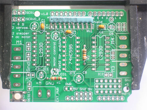
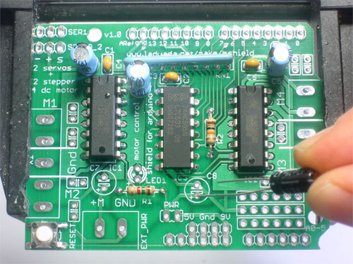
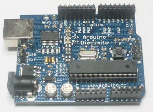
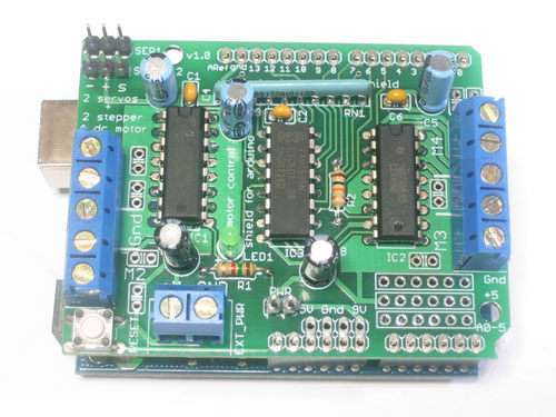
Next is the 6mm tactile switch RESET and the resistor network RN1. The tact switch is used to reset the Arduino since its not possible to reach the reset button once the motor shield is on.
The resistor network is used to pull-down the pins on the motor driver chips so that they don't power up the motors before the Arduino sketch tells them to.
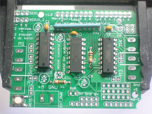
The tactile switch can go in 'either way'. The resistor network, however, must go in a certain way. Make sure the end with a dot is posititioned so it is at the same end as the X in the silkscreened image of the resistor network. (See picture on left)
Traduit avec l'autorisation d'AdaFruit Industries - Translated with the permission from Adafruit Industries - www.adafruit.com
Toute référence, mention ou extrait de cette traduction doit être explicitement accompagné du texte suivant : « Traduction par MCHobby (www.MCHobby.be) - Vente de kit et composants » avec un lien vers la source (donc cette page) et ce quelque soit le média utilisé.
L'utilisation commercial de la traduction (texte) et/ou réalisation, même partielle, pourrait être soumis à redevance. Dans tous les cas de figures, vous devez également obtenir l'accord du(des) détenteur initial des droits. Celui de MC Hobby s'arrêtant au travail de traduction proprement dit.
