Différences entre versions de « Arduino Robot »
(→Power) |
|||
| Ligne 78 : | Ligne 78 : | ||
Les fichiers EAGLE pour la carte de contrôle et la carte moteur: [http://arduino.cc/en/uploads/Main/arduino-robot-reference-design_3b1.zip arduino-robot-reference-design.zip] | Les fichiers EAGLE pour la carte de contrôle et la carte moteur: [http://arduino.cc/en/uploads/Main/arduino-robot-reference-design_3b1.zip arduino-robot-reference-design.zip] | ||
| − | == | + | == Alimentation == |
| − | + | Le Robot Arduino peut être alimenté par l'intermédaire de la connexion USB ou avec 4 piles AA. La source d'alimentation est sélectionné automatiquement. | |
| − | + | Le support de piles est capable de recevoir 4 piles AA rechargable NiMh. | |
| − | + | {{ambox-stop|text=N'utilisez pas de piles non-rechargable avec le robot!}} | |
| − | + | Pour des raisons de sécurité, les moteurs sont désactivés lorsque le robot est alimenté par USB. | |
| − | + | La carte du robot dispose d'un rechargeur d'accumulateur (pile rechargeable) nécessitant une alimentation externe de 9v (tension fournie par un bloc d'alimentation AC-vers-DC). Le bloc d'alimentation peut être connecté en utilisant une fiche jack de 2.1mm center-positif qui se branche sur la prise correspondante sur la carte moteur. Le chargeur est désactivé sur le Robot est alimenté par USB. | |
| − | + | La carte de contrôle est alimentée par l'alimentation de la carte moteur. | |
== Memory == | == Memory == | ||
Version du 1 septembre 2013 à 19:05
|
|
En cours de traduction/élaboration. |
Description
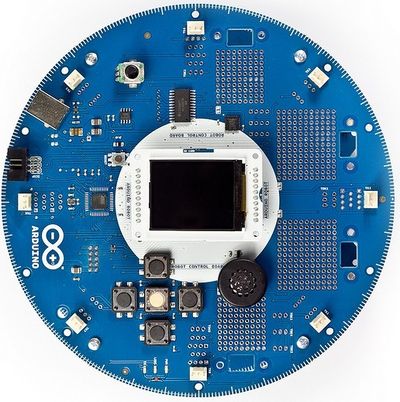
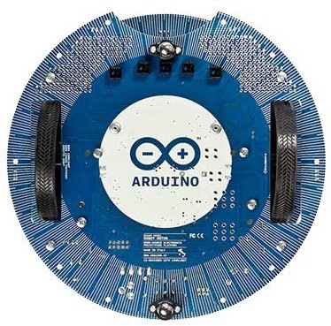
Arduino Robot est le premier vrai Arduino sur roue. Le robot dispose de deux processeur, chacun sur sa propre carte. La carte moteur , et la carte de controle lisant les senseurs et décidant des opérations à suivre. Cacune des cartes est un Arduino totalement programmable à l'aide d'Arduino IDE.
 Crédit: Arduino arduino.cc |
 Crédit: Arduino arduino.cc |
Les deux cartes Moteur et Controle sont des cartes basées sur le microcontroleur ATmega32u4 (fiche technique, source Atmel). Le robot dispose de nombreuses broches/pin déjà attachées aux senseurs et actuateurs placés sur les cartes.
Programmer le robot est un processus for similaire à la programmation d'un Arduino Leonardo. Les deux processeurs du robot disposent d'un support USB intégré, éliminant ainsi be besoin d'un second processeur dédié à la communication USB comme c'est le cas pour Arduino Uno. Grâce à cela, le Robot apparait connecté à l'ordinateur comme un port série virtuel (CDC) / port COM.
Comme c'est le cas pour Arduino, chaque élement de la plateforme – matériel, logiciel et documentation – est librement accessible et open-source. MCHobby en propose d'ailleurs des traductions. Cela vous permet d'étudier la conception et de comprendre le fonctionnement du robot, ce qui vous permet d'élaborer votre propre projet. Arduino Robot est le résultat d'un effort collectif réalisé par une équipe internationale s'attachant à rendre la science intéressante.
Arduino est maintenant monté sur roue... venez nous aider à les faire rouler!
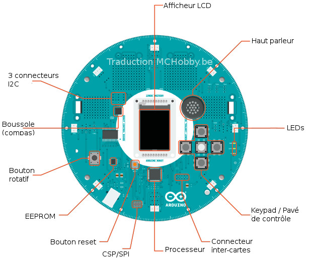
Détails techniques de la carte de contrôle
- Microcontrolleur: ATmega32u4
- Tension de fonctionnement: 5V
- Tension d'entrée: 5V via le câble plat.
- Entrée/Sortie digital: 5
- Canaux de sortie PWM: 6
- Canaux d'entrée Analogique: 4 (des broches d'entrée/sortie digitals)
- Canaux d'entrée analogique (multiplexée): 8
- Courant continu par broche d'entrée/sortie: 40 mA
- Mémoire Flash: 32 KB (ATmega32u4) dont 4 KB réservé au bootloader
- SRAM: 2.5 KB (ATmega32u4)
- EEPROM (interne): 1 KB sur ATmega32u4
- EEPROM (externe): 512 Kbit via I2C
- Vitesse d'horloge: 16 MHz
- Keypad: 5 touches
- Potentiomètre attaché à une broche analogique
- Un afficheur LCD Couleur via interface de communication SPI
- Lecteur de carte SD pour les cartes SD formattées en FAT16
- Haut parleur: 8 Ohm
- Boussole digitale (Digital Compass) fournissant la déviation en degrés par rapport au nord.
- Ports I2C : 3 connecteurs
- Zone de prototypage: 4
Crédit: Arduino arduino.cc
Traduction MCHobby.be
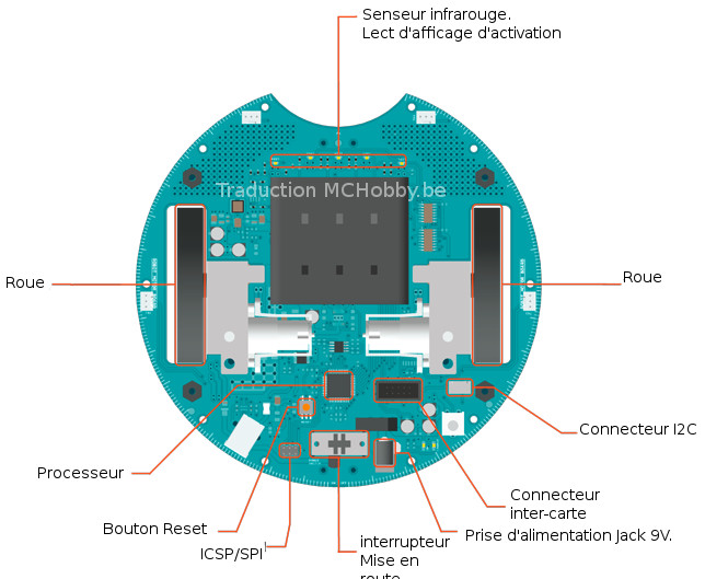
Détails techniques de la carte moteur
- Microcontrolleur: ATmega32u4
- Tension de fonctionnement: 5V
- Tension d'entrée: 9V via un chargeur d'accumulateur.
- Support de pile AA: pour 4 alkaline ou pile rechageable NiMh
- Broches d'entrée/sortie digitales: 4
- Canaux PWM: 1
- Canaux d'entrée analogique: 4 (même que les broches d'entrée/sortie digitals)
- Courant continu par broche: 40 mA
- Convertisseur DC-DC, permet de générer du 5V pour alimenter tout le robot
- Mémoire Flash: 32 KB (ATmega32u4) dont 4 KB réservé pour le bootloader
- SRAM: 2.5 KB (ATmega32u4)
- EEPROM: 1 KB (ATmega32u4)
- Vitesse d'horloge: 16 MHz
- Potentiomètre de réglage (Trimmer) pour calibrer et corriger la dérive.
- Senseur InfraRouge pour le suivit de ligne: 5
- Port I2C: 1 connecteur
- Surface de prototypage: 2
Crédit: Arduino arduino.cc
Traduction MCHobby.be
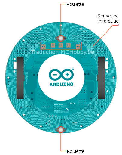
Crédit: Arduino arduino.cc
Traduction MCHobby.be
Schéma et référence
Les fichiers EAGLE pour la carte de contrôle et la carte moteur: arduino-robot-reference-design.zip
Alimentation
Le Robot Arduino peut être alimenté par l'intermédaire de la connexion USB ou avec 4 piles AA. La source d'alimentation est sélectionné automatiquement.
Le support de piles est capable de recevoir 4 piles AA rechargable NiMh.
| N'utilisez pas de piles non-rechargable avec le robot! |
Pour des raisons de sécurité, les moteurs sont désactivés lorsque le robot est alimenté par USB.
La carte du robot dispose d'un rechargeur d'accumulateur (pile rechargeable) nécessitant une alimentation externe de 9v (tension fournie par un bloc d'alimentation AC-vers-DC). Le bloc d'alimentation peut être connecté en utilisant une fiche jack de 2.1mm center-positif qui se branche sur la prise correspondante sur la carte moteur. Le chargeur est désactivé sur le Robot est alimenté par USB.
La carte de contrôle est alimentée par l'alimentation de la carte moteur.
Memory
The ATmega32u4 has 32 KB (with 4 KB used for the bootloader). It also has 2.5 KB of SRAM and 1 KB of EEPROM (which can be read and written with the EEPROM library).
The Control Board has an extra 512 Kbit EEPROM that can be accessed via I2C.
There is an external SD card reader attached to the GTFT screen that can be accessed by the Control Board's processor for additional storage.
Entrée et sortie
Input and Output
The Robot comes with a series of pre-soldered connectors. There are a number of additional spots for you to install additional parts if needed.
All the connectors are labelled on the boards and mapped to named ports through the Robot library allowing access to standard Arduino functions. Each pin can provide or receive a maximum of 40mA at 5V.
Some pins have specialized functions :
Control Board TK0 to TK7
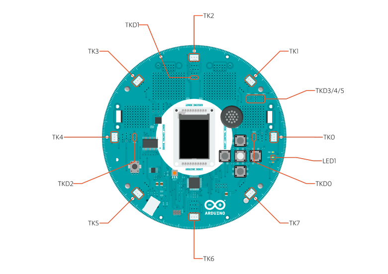
Crédit: Arduino arduino.cc
these pins are multiplexed to a single analog pin on theControl Board's microprocessor. They can be used as analog inputs for sensors like distance sensors, analog ultrasound sensors, or mechanical switches to detect collisions.
Control Board TKD0 to TKD5

Crédit: Arduino arduino.cc
these are digital I/O pins directly connected to the processor, addressed using Robot.digitalRead() and Robot.digitalWrite() functions. Pins TKD0 to TKD3 can also be used as analog inputs with Robot.analogRead()
Note: if you have one of the first generation robots, you will see that the TKD* pins are named TDK* on the Robot's silkscreen. TKD* is the proper name for them and is how we address them on the software.
Motor Board TK1 to TK4

Crédit: Arduino arduino.cc
these pins are named in software as B_TK1 to B_TK4, they can be digital or analog input pins, and support Robot.digitalRead(), Robot.digitalWrite) and Robot.analogRead().
Serial Communication
The boards communicate with each other using the processors' serial port. A 10-pin connector connects both boards carries the serial communication, as well as power and additional information like the battery's current charge.
Control Board SPI
SPI is used to control the GTFT and SD card. If you want to flash the processor using an external programmer, you need to disconnect the screen first.
Control Board LEDs
the Control Board has three on-board LEDs. One indicates the board is powered (PWR). The other two indicate communication over the USB port (LED1/RX and TX). LED1 is also accessible via software.
I2C
Both boards have I2C connectors available: 3 on the Control Board and 1 on the Motor Board.
Control Board Pin Mapping
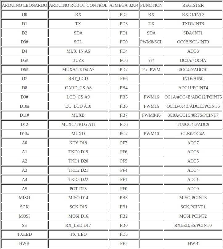
Crédit: Arduino arduino.cc
Motor Board Pin Mapping
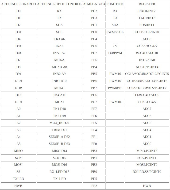
Crédit: Arduino arduino.cc
Communication
The Robot has a number of facilities for communicating with a computer, another Arduino, or other microcontrollers. The ATmega32U4 provides UART TTL (5V) serial communication, which is available on digital the 10-pin board-to-board connector. The 32U4 also allows for serial (CDC) communication over USB and appears as a virtual com port to software on the computer. The chip also acts as a full speed USB 2.0 device, using standard USB COM drivers. On Windows, a .inf file is required. The Arduino software includes a serial monitor which allows simple textual data to be sent to and from the Robot board. The RX (LED1) and TX LEDs on the board will flash when data is being transmitted via the USB connection to the computer (but not for serial communication between boards).
Each one of the boards has a separate USB product identifier and will show up as different ports on you IDE. Make sure you choose the right one when programming.
The ATmega32U4 also supports I2C (TWI) and SPI communication. The Arduino software includes a Wire library to simplify use of the I2C bus; see the documentation for details. For SPI communication, use the SPI library.
Programming
The Robot can be programmed with the Arduino software (download). Select "Arduino Robot Control Board" or "Arduino Robot Motor Board" from the Tools > Board menu. For details, voir le guide démarrage et les tutoriels arduino (Anglais, Arduino.cc) ou les tutoriels Arduino proposé par MCHobby.
The ATmega32U4 processors on the Arduino Robot come preburned with a bootloader that allows you to upload new code to it without the use of an external hardware programmer. It communicates using the AVR109 protocol.
You can bypass the bootloader and program the microcontroller through the ICSP (In-Circuit Serial Programming) header; voir ces instructions pour plus de détails (Anglais, Arduino.cc).
Automatic (Software) Reset and Bootloader Initiation
Rather than requiring a physical press of the reset button before an upload, the Robot is designed in a way that allows it to be reset by software running on a connected computer. The reset is triggered when the Robot's virtual (CDC) serial / COM port is opened at 1200 baud and then closed. When this happens, the processor will reset, breaking the USB connection to the computer (meaning that the virtual serial / COM port will disappear). After the processor resets, the bootloader starts, remaining active for about 8 seconds. The bootloader can also be initiated by double-pressing the reset button on the Robot. Note that when the board first powers up, it will jump straight to the user sketch, if present, rather than initiating the bootloader.
Because of the way the Robot handles reset it's best to let the Arduino software try to initiate the reset before uploading, especially if you are in the habit of pressing the reset button before uploading on other boards. If the software can't reset the board you can always start the bootloader by double-pressing the reset button on the board. A single press on the reset will restart the user sketch, a double press will initiate the bootloader.
USB Overcurrent Protection
Both of the Robot boards have a resettable polyfuse that protects your computer's USB ports from shorts and overcurrent. Although most computers provide their own internal protection, the fuse provides an extra layer of protection. If more than 500 mA is applied to the USB port, the fuse will automatically break the connection until the short or overload is removed.
Physical Characteristics
The Robot is 19cm in diameter. Including wheels, GTFT screen and other connectors it can be up to 10cm tall.
Pour poursuivre
Voir aussi le Guide Démarrage et la Librairie.
Source: Arduino Robot, getting started with the Arduino Robot, the Robot's library pages. Crédit: Arduino.cc, licence Creative Common Attribution ShareAlike.
Toute référence, mention ou extrait de cette traduction doit être explicitement accompagné du texte suivant : « Traduction par MCHobby (www.MCHobby.be) - Vente de kit et composants » avec un lien vers la source (donc cette page) et ce quelque soit le média utilisé.
L'utilisation commercial de la traduction (texte) et/ou réalisation, même partielle, pourrait être soumis à redevance. Dans tous les cas de figures, vous devez également obtenir l'accord du(des) détenteur initial des droits. Celui de MC Hobby s'arrêtant au travail de traduction proprement dit.