RASP-FT232H-Assembler
|
|
En cours de traduction/élaboration. |
Assembler
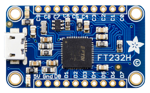
To assemble the FT232H breakout you'll need to solder the included headers to the breakout board. If you haven't soldered before, make sure to first read the guide to excellent soldering and try practicing with some scrap wires and components.
Start by trimming the male headers to the length of the pin holes on the breakout board. You should have two rows of male headers with 10 pins each.
Then insert the longer pins of the headers into a breadboard so that the pin holes on the FT232H breakout slide perfectly through the header pins sticking out the top of the breadboard.
Using a soldering iron and some solder, carefully solder all the pins to the FT232H breakout board.
xxx décrire xxx If you aren't clear on the steps above, check out an assembly guide for other breakout boards like the VS1053 audio board. You should follow the same steps to solder the header pins to the FT232H breakout board.
Once the headers are soldered to the board, plug in a micro USB cable to the port on the FT232H breakout and then plug the cable into a computer or laptop. You should see a green LED next to the 5V pin on the breakout light up. Congratulations your FT232H board is assembled!
Brancher
Below is a quick description of the pins on the FT232H breakout. You'll learn about these pins in more detail in the Serial UART and MPSSE Setup sections of the guide.
- 5V - This is a 5 volt power source connected directly to the USB bus. Don't pull more than about 400-500mA of current from this pin or else you might damage your computer's USB port!
- GND - This is the ground of the FT232H breakout.
- D0 à D7 - These are the ADBUS pins on the FT232H chip and are used for the serial UART and other serial protocols. You can also use some of them as GPIO pins for digital inputs and outputs.
- C0 à C9 - These are the ACBUS pins on the FT232H chip and are mainly used as GPIO pins for digital inputs and outputs. Note that pins C8 and C9 are not controlled by software and can only be assigned functionality by changing the EEPROM of the chip. You'll learn more about these two pins in the more info section.
Source: Adafruit FT232H Breakout Add a serial protocol 'swiss army knife' to your computer and talk directly to devices with SPI, I2C, serial UART, GPIO's, and more!
Créé par Toni DiCola pour AdaFruit Industries.
Traduction réalisée par Meurisse D pour MCHobby.be.
Toute référence, mention ou extrait de cette traduction doit être explicitement accompagné du texte suivant : « Traduction par MCHobby (www.MCHobby.be) - Vente de kit et composants » avec un lien vers la source (donc cette page) et ce quelque soit le média utilisé.
L'utilisation commercial de la traduction (texte) et/ou réalisation, même partielle, pourrait être soumis à redevance. Dans tous les cas de figures, vous devez également obtenir l'accord du(des) détenteur initial des droits. Celui de MC Hobby s'arrêtant au travail de traduction proprement dit.
Traduit avec l'autorisation d'AdaFruit Industries - Translated with the permission from Adafruit Industries - www.adafruit.com
