Rasp-Hack-Afficheur-LCD-Python
|
|
En cours de traduction/élaboration. |
Pre-requis
Sur un Raspberry-Pi, vous aurez besoin d'installer le minimum logiciel pour pouvoir télécharger la bibliothèque Adafruit.
sudo apt-get update
sudo apt-get install build-essential python-dev python-smbus python-pip git
sudo pip install RPi.GPIO
Installation de la bibliothèque
Une fois les dépendances ci-dessus installées, vous pouvez installer le module LCD Alphanumerique en exécutant les commandes suivantes sur votre appareil:
cd ~
git clone https://github.com/adafruit/Adafruit_Python_CharLCD.git
cd Adafruit_Python_CharLCD
sudo python setup.py install
Ces commandes vont dupliquer (cloner) les source de la bibliothèque depuis GitHub puis exécuter le script setup.py pour installer la bibliothèque dans python.
Avec un LCD standard
Once the library is installed you can find a few examples of its usage in the examples subdirectory. If you're using a monochrome backlight LCD (i.e. single color, like a white on blue LCD) the char_lcd.py script will demonstrate the basic usage.
If you're using a Raspberry Pi and have wired it according to this guide, you can immediately run the example. However if you're using a BeagleBone Black or changed the wiring, first open char_lcd.py in a text editor (like nano) and uncomment/comment the lines towards the top that set the LCD pins.
Note: If you're using a BeagleBone Black wired for hardware PWM of the backlight, skip down the page to the section on using hardware PWM.
To run the example execute:
cd examples
python char_lcd.py
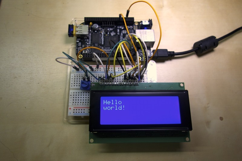
You should see the LCD backlight turn on and messages printed to the display. For example below is what you will see with a 20x4 blue backlight LCD:

Crédit: AdaFruit Industries www.adafruit.com
To demonstrate the usage of the library I'll walk through the source code of the char_lcd.py example below.
import math
import time

import Adafruit_CharLCD as LCD
The first part of the script are commands to import modules that will be used. In particular the Adafruit_CharLCD module is imported under the name LCD. Later in the script you can see how classes from the char LCD module are used to interact with the LCD.
# Raspberry Pi pin configuration:
lcd_rs        = 27  # Note this might need to be changed to 21 for older revision Pi's.
lcd_en        = 22
lcd_d4        = 25
lcd_d5        = 24
lcd_d6        = 23
lcd_d7        = 18
lcd_backlight = 4

# BeagleBone Black configuration:
# lcd_rs        = 'P8_8'
# lcd_en        = 'P8_10'
# lcd_d4        = 'P8_18'
# lcd_d5        = 'P8_16'
# lcd_d6        = 'P8_14'
# lcd_d7        = 'P8_12'
# lcd_backlight = 'P8_7'
The next part of the script configures which pins are connected to the LCD. You can see the Raspberry Pi configuration is uncommented by default, and below it the BeagleBone Black configuration is commented. You can use any digital GPIO pins in the configuration.
# Define LCD column and row size for 16x2 LCD.
lcd_columns = 16
lcd_rows    = 2

# Alternatively specify a 20x4 LCD.
# lcd_columns = 20
# lcd_rows    = 4
This section of the script configures the size of the LCD. By default the code assumes a 16 column, 2 row LCD however you can adjust the configuration to a 20x4 or other size display supported by the HD44780.
# Initialize the LCD using the pins above.
lcd = LCD.Adafruit_CharLCD(lcd_rs, lcd_en, lcd_d4, lcd_d5, lcd_d6, lcd_d7,
                           lcd_columns, lcd_rows, lcd_backlight)
Next an instance of the Adafruit_CharLCD class is created based on the configuration specified earlier in the script.
# Print a two line message
lcd.message('Hello\nworld!')

# Wait 5 seconds
time.sleep(5.0)

# Demo showing the cursor.
lcd.clear()
lcd.show_cursor(True)
lcd.message('Show cursor')

time.sleep(5.0)

# Demo showing the blinking cursor.
lcd.clear()
lcd.blink(True)
lcd.message('Blink cursor')

time.sleep(5.0)

# Stop blinking and showing cursor.
lcd.show_cursor(False)
lcd.blink(False)
The next lines demonstrate basic usage of the LCD display class. The message function can be used to write a string of text to the display (including support for line breaks). The clear function clears the display, and the show_cursor and blink functions specify if the cursor is shown and should blink.
Although not shown above, there are other functions you might find useful on the LCD class. To see details on all functions you can have Python print help text for the class by executing (ignore the >>> prompt, it's only shown for reference as the Python interpreter):
python
>>> import Adafruit_CharLCD as LCD
>>> help(LCD.Adafruit_CharLCD)
You should see a description of each function on the LCD class, including some functions not shown in the example:
autoscroll(autoscroll)
Autoscroll will 'right justify' text from the cursor if set True, otherwise it will 'left justify' the text.
enable_display(enable)
Enable or disable the display. Set enable to True to enable.
home()
Move the cursor back to its home (first line and first column).
set_backlight(backlight)
Enable or disable the backlight. If PWM is not enabled (default), a non-zero backlight value will turn on the backlight and a zero value will turn it off. If PWM is enabled, backlight can be any value from 0.0 to 1.0, with 1.0 being full intensity backlight.
set_cursor(col, row)
Move the cursor to an explicit column and row position.
Finally, the last portion of the char_lcd.py script:
# Demo scrolling message right/left.
lcd.clear()
message = 'Scroll'
lcd.message(message)
for i in range(lcd_columns-len(message)):
	time.sleep(0.5)
	lcd.move_right()
for i in range(lcd_columns-len(message)):
	time.sleep(0.5)
	lcd.move_left()

# Demo turning backlight off and on.
lcd.clear()
lcd.message('Flash backlight\nin 5 seconds...')
time.sleep(5.0)
# Turn backlight off.
lcd.set_backlight(0)
time.sleep(2.0)
# Change message.
lcd.clear()
lcd.message('Goodbye!')
# Turn backlight on.
lcd.set_backlight(1)
You can see how the move_right and move_left functions are used to scroll the display, and further down how the set_backlight function turns off and on the backlight.
That's all there is to using the Adafruit_CharLCD class!
Avec un LCD RGB
If you're using an RGB backlight LCD the char_lcd_rgb.py script will demonstrate the usage.
If you're using a Raspberry Pi and have wired it according to this guide, you can immediately run the script. However if you're using a BeagleBone Black or have changed the wiring, edit the script with a text editor and uncomment/change the lines at the top that define the LCD pins.
To execute the RGB backlight example run this command from inside the examples directory:
sudo python char_lcd_rgb.py
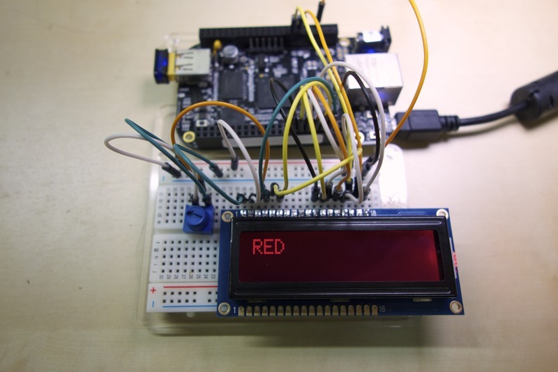
You should see the LCD turn on and display different backlight colors. For example:

Crédit: AdaFruit Industries www.adafruit.com
If you open the file char_lcd_rgb.py in a text editor (such as nano) I'll describe the important differences between it and the previous char_lcd.py example below.
# Example Raspberry Pi configuration:
lcd_rs = 27  # Change this to pin 21 on older revision Raspberry Pi's
lcd_en = 22
lcd_d4 = 25
lcd_d5 = 24
lcd_d6 = 23
lcd_d7 = 18
lcd_red   = 4
lcd_green = 17
lcd_blue  = 7  # Pin 7 is CE1

# Example BeagleBone Black configuration:
# lcd_rs = 'P8_8'
# lcd_en = 'P8_10'
# lcd_d4 = 'P8_18'
# lcd_d5 = 'P8_16'
# lcd_d6 = 'P8_14'
# lcd_d7 = 'P8_12'
# lcd_red   = 'P8_7'
# lcd_green = 'P8_9'
# lcd_blue  = 'P8_11'
The first important difference is the configuration of LCD pins. Notice there are now explicit pins defined for the red, green, and blue backlight LEDs.
# Initialize the LCD using the pins
lcd = LCD.Adafruit_RGBCharLCD(lcd_rs, lcd_en, lcd_d4, lcd_d5, lcd_d6, lcd_d7,
                              lcd_columns, lcd_rows, lcd_red, lcd_green, lcd_blue)
The next line creates an instance of the Adafruit_RGBCharLCD class using the pin configuration defined earlier.
The Adafruit_RGBCharLCD class inherits from the Adafruit_CharLCD class so it has all the same functionality as demonstrated in the char_lcd.py example. In addition to the basic character LCD functionality the RGB character LCD class adds some functions to set the RGB color of the backlight.
# Show some basic colors.
lcd.set_color(1.0, 0.0, 0.0)
lcd.clear()
lcd.message('RED')
time.sleep(3.0)

lcd.set_color(0.0, 1.0, 0.0)
lcd.clear()
lcd.message('GREEN')
time.sleep(3.0)

lcd.set_color(0.0, 0.0, 1.0)
lcd.clear()
lcd.message('BLUE')
time.sleep(3.0)

lcd.set_color(1.0, 1.0, 0.0)
lcd.clear()
lcd.message('YELLOW')
time.sleep(3.0)

lcd.set_color(0.0, 1.0, 1.0)
lcd.clear()
lcd.message('CYAN')
time.sleep(3.0)

lcd.set_color(1.0, 0.0, 1.0)
lcd.clear()
lcd.message('MAGENTA')
time.sleep(3.0)

lcd.set_color(1.0, 1.0, 1.0)
lcd.clear()
lcd.message('WHITE')
time.sleep(3.0)
The code above demonstrates each basic color by calling the set_color function and passing in which red, green, and blue LEDs to enable. For example the first call to set_color(1.0, 0.0, 0.0) will turn on the red LED and turn off the green and blue LED so the backlight will have a red color.
Notice how later lines combine multiple LEDs to get different colors, like calling set_color(1.0, 0.0, 1.0) to combine red and blue LEDs for a magenta/violet color.
Avec un MCP23017 + LCD
Si vous avez suivi le plan de montage avec le MCP23017 alors c'est cette partie du tutoriel qui vous intéresse.
|
|
En cours de traduction/élaboration. |
The char_lcd_mcp.py file in the library's examples folder demonstrates the usage of a character LCD (non-RGB version) with an MCP23017 IO extender. Run the script by executing this command inside the examples directory:
sudo python char_lcd_mcp.py
You should see a simple demo of the LCD displaying text, cursors, and scrolling just like the char_lcd.py demo described on the previous page.
If you open char_lcd_mcp.py in a text editor you can see how to use the character LCD library with the MCP chip. Below is an overview of the file:
import math
import time

import Adafruit_CharLCD as LCD
import Adafruit_GPIO.MCP230xx as MCP
First the required modules are imported. Notice the addition of the Adafruit_GPIO.MCP230xx module (imported under the name MCP). This MCP230xx class will be used to talk to the MCP chip and interface with the LCD.
# Define MCP pins connected to the LCD.
lcd_rs        = 0
lcd_en        = 1
lcd_d4        = 2
lcd_d5        = 3
lcd_d6        = 4
lcd_d7        = 5
lcd_backlight = 6
# Optionally if the backlight is not controllable then set:
# lcd_backlight = None

# Define LCD column and row size for 16x2 LCD.
lcd_columns = 16
lcd_rows    = 2

# Alternatively specify a 20x4 LCD.
# lcd_columns = 20
# lcd_rows    = 4
Next the LCD pins are defined in the script. Note that these pin numbers are the MCP chip GPIO pin numbers, and NOT Raspberry Pi/BeagleBone Black pin numbers!
# Initialize MCP23017 device using its default 0x20 I2C address.
gpio = MCP.MCP23017()

# Alternatively you can initialize the MCP device on another I2C address or bus.
# gpio = MCP.MCP23017(0x24, busnum=1)
Next an instance of the MCP23017 class is created. By default this class will use the I2C address 0x20 (default for MCP chips) and appropriate I2C bus for the running development board. However if you need to override the address or bus number you can see in the commented line how these are passed as parameters.
Also note if you're using an MCP23008 chip you can instead create an instance of the MCP23008 class. This class is exactly the same as the MCP23017 class, but only supports 8 GPIO pins.
Now the Adafruit_CharLCD class instance is created. The big difference with this line and previous examples is that the MCP23017 class (created with the name 'gpio') is passed in as the gpio parameter. By passing in an explicit gpio parameter, the char LCD class will use that GPIO class for talking to the LCD instead of the default development board GPIO pins.
The rest of the example code is exactly the same as the non-MCP character LCD example. You only need to change the setup and initialization of the character LCD class to use the MCP IO extender with an LCD!
| Note you can also use an RGB character LCD with an MCP IO extender, however the MCP IO extender does NOT support PWM control of the backlight! |
L'exemple Horloge + IP
| Ce script par du principe que c'est l'adresse IP de la connexion filaire Ethernet (eth0) qui sera affichée. Vous pourriez avoir envie de remplacer eth0 par wlan0 ou wlan1 (etc) pour les adresses IP des réseaux Wifi! |
#!/usr/bin/python

from Adafruit_CharLCD import Adafruit_CharLCD
from subprocess import *
from time import sleep, strftime
from datetime import datetime

lcd = Adafruit_CharLCD()

cmd = "ip addr show eth0 | grep inet | awk '{print $2}' | cut -d/ -f1"

lcd.begin(16,1)

def run_cmd(cmd):
    p = Popen(cmd, shell=True, stdout=PIPE)
    output = p.communicate()[0]
    return output

while 1:
    lcd.clear()
    ipaddr = run_cmd(cmd)
    lcd.message(datetime.now().strftime('%b %d %H:%M:%S\n'))
    lcd.message('IP %s' % ( ipaddr ) )
    sleep(2)
Executer le code
Démarrer l'exemple IP + horloge
$ sudo ./Adafruit_CharLCD_IPclock_example.py
Résultat
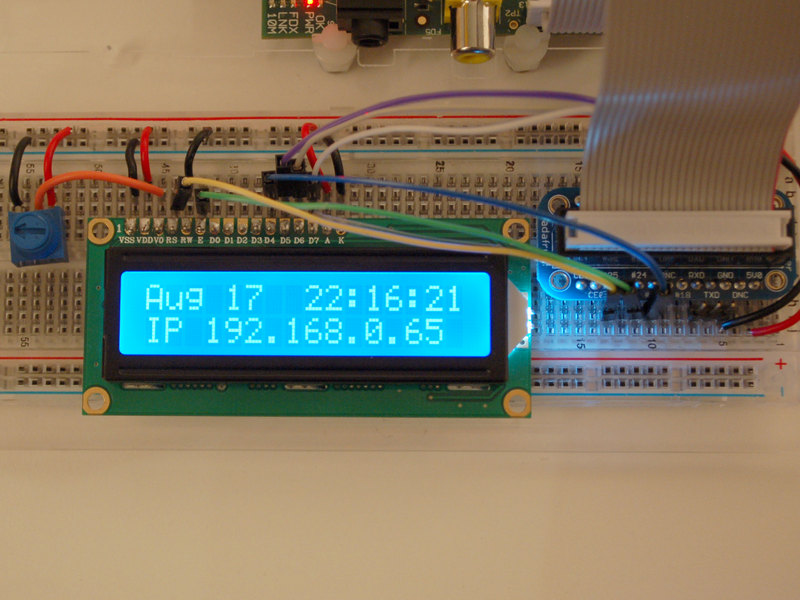
Ce que vous devriez voir:
Source: Character LCD with Raspberry Pi or BeagleBone Black écrit par Tony Dicola pour Adafruit Industries.
Traduit avec l'autorisation d'AdaFruit Industries - Translated with the permission from Adafruit Industries - www.adafruit.com
Toute référence, mention ou extrait de cette traduction doit être explicitement accompagné du texte suivant : « Traduction par MCHobby (www.MCHobby.be) - Vente de kit et composants » avec un lien vers la source (donc cette page) et ce quelque soit le média utilisé.
L'utilisation commercial de la traduction (texte) et/ou réalisation, même partielle, pourrait être soumis à redevance. Dans tous les cas de figures, vous devez également obtenir l'accord du(des) détenteur initial des droits. Celui de MC Hobby s'arrêtant au travail de traduction proprement dit.
