Différences entre versions de « Rasp-PiGRRL-2-Gamepad »
(Page créée avec « {{Rasp-PiGRRL-2-NAV}} {{traduction}} {{Rasp-PiGRRL-2-TRAILER}} ») |
|||
| Ligne 2 : | Ligne 2 : | ||
{{traduction}} | {{traduction}} | ||
| + | |||
| + | == PiGRRL Gamepad Design == | ||
| + | {{ADFImage|Rasp-PiGRRL-2-Gamepad-01.jpg|640px}} | ||
| + | |||
| + | The gamepad was designed in EagleCAD and available to download and modify. It's also a shared project on Oshpark. | ||
| + | |||
| + | {{ADFImage|Rasp-PiGRRL-2-Gamepad-02.png|640px}} | ||
| + | |||
| + | == PiGRRL Gamepad PCB == | ||
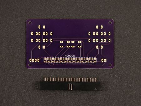
| + | Let's start assembly by putting the gamepad together. Gather up 10x 6mm tactile buttons and a 40pin IC box header. | ||
| + | |||
| + | |||
| + | {{asm-begin}} | ||
| + | {{asm-row|img=Rasp-PiGRRL-2-Gamepad-03.jpg}} | ||
| + | {{asm-img|img=Rasp-PiGRRL-2-Gamepad-04.jpg}} | ||
| + | {{asm-img|img=Rasp-PiGRRL-2-Gamepad-05.jpg}} | ||
| + | {{asm-text}} | ||
| + | '''Install IC Box Header''' | ||
| + | |||
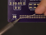
| + | Insert the box header into the header labeled pin on the back of the gamepad PCB. Make sure the "notch" opening is pointing towards the "header" label. Secure it in place by adding mounting tack to the sides. Now we can secure the PCB to a Panavise to assist while soldering. | ||
| + | |||
| + | {{asm-row|img=Rasp-PiGRRL-2-Gamepad-06.jpg}} | ||
| + | {{asm-img|img=Rasp-PiGRRL-2-Gamepad-07.jpg}} | ||
| + | {{asm-img|img=Rasp-PiGRRL-2-Gamepad-08.jpg}} | ||
| + | {{asm-text}} | ||
| + | '''Solder IC Box Header''' | ||
| + | |||
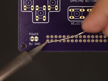
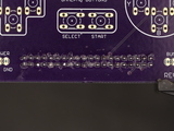
| + | Flip the gamepad PCB over so the header pins are facing up. Now heat up the soldering iron and apply solder to each of the 40 pins on the header. Ensure the solder joints are clean with no cold solder joints or blobs. They should look like Hershey's Kisses. | ||
| + | |||
| + | {{asm-end}} | ||
| + | {{ADFImage|Rasp-PiGRRL-2-Gamepad-09.jpg|640px}} | ||
| + | |||
| + | == Prep 6mm Tactile Buttons == | ||
| + | To make it easier to insert the buttons to the PCB, use a pair of flat plier to straighten out the four leads of each button. | ||
| + | |||
| + | {{asm-begin}} | ||
| + | {{asm-row|img=Rasp-PiGRRL-2-Gamepad-10.jpg}} | ||
| + | {{asm-img|img=Rasp-PiGRRL-2-Gamepad-11.jpg}} | ||
| + | {{asm-img|img=Rasp-PiGRRL-2-Gamepad-12.jpg}} | ||
| + | {{asm-text}} | ||
| + | '''Install 6mm Tactile Buttons''' | ||
| + | |||
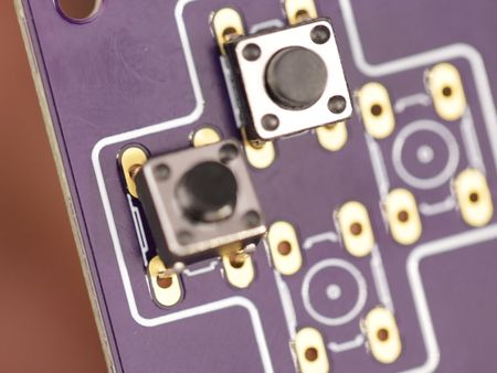
| + | Insert each button into the through-hole spots on the gamepad PCB. Once installed, place your hand over the buttons and bend each of the leads inward so they "bite" onto the PCB - This will help hold them in place. | ||
| + | |||
| + | {{asm-row|img=Rasp-PiGRRL-2-Gamepad-13.jpg}} | ||
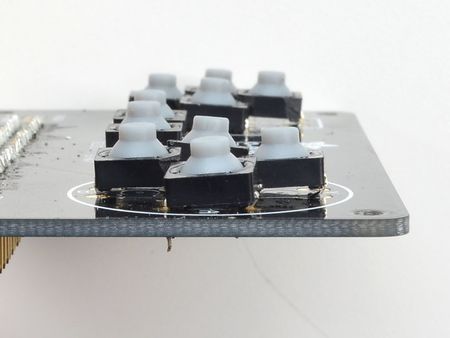
| + | {{asm-text}}If you are using the elastomer buttons, they're still possible to use, but they wont sit perfectly flat. That's OK just make them as flat as you can! | ||
| + | |||
| + | {{asm-row|img=Rasp-PiGRRL-2-Gamepad-14.jpg}} | ||
| + | {{asm-text}} | ||
| + | '''Solder Buttons to Gamepad PCB''' | ||
| + | |||
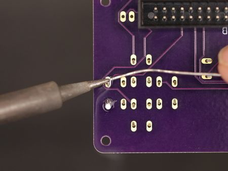
| + | Secure the gamepad PCB to a Panavise and solder up the buttons. Make sure solder joints are clean like you did on the pins of the IC box header. | ||
| + | |||
| + | {{asm-end}} | ||
| + | {{ADFImage|Rasp-PiGRRL-2-Gamepad-15.jpg|640px}} | ||
| + | |||
| + | == Soldered Gamepad PCB == | ||
| + | Here's what the soldered gamepad will look like. Clean and Shiny! | ||
| + | |||
| + | {{ADFImage|Rasp-PiGRRL-2-Gamepad-16.jpg|640px}} | ||
| + | |||
| + | == Tap Gamepad PCB Mounting Holes == | ||
| + | Now is a good time to tap the mounting holes of the gamepad PCB. We need to create threads on each hole so that it's easier to mount to the case. You can use a #4-40 sized tap tool, or a #4-40 machine screw to do this, just make sure to fasten as straight as you can. | ||
| + | |||
{{Rasp-PiGRRL-2-TRAILER}} | {{Rasp-PiGRRL-2-TRAILER}} | ||
Version du 5 février 2018 à 22:15
|
|
En cours de traduction/élaboration. |
PiGRRL Gamepad Design
Crédit: AdaFruit Industries www.adafruit.com
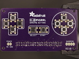
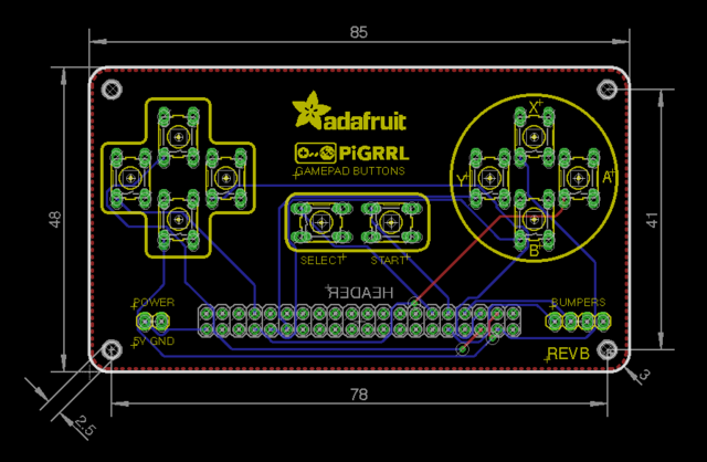
The gamepad was designed in EagleCAD and available to download and modify. It's also a shared project on Oshpark.
Crédit: AdaFruit Industries www.adafruit.com
PiGRRL Gamepad PCB
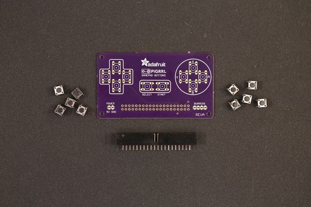
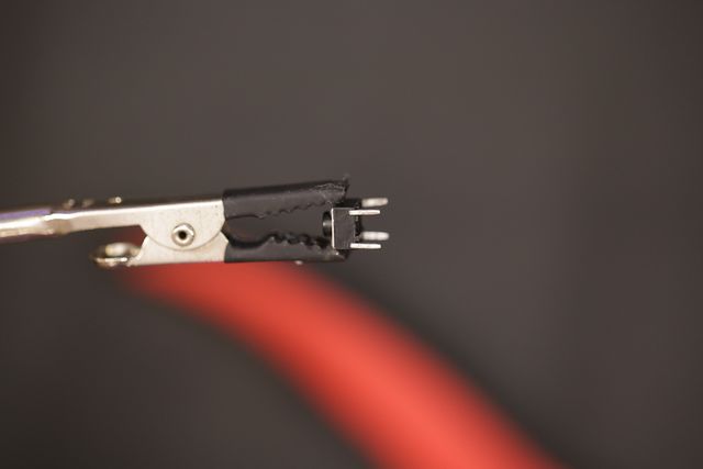
Let's start assembly by putting the gamepad together. Gather up 10x 6mm tactile buttons and a 40pin IC box header.
Crédit: AdaFruit Industries www.adafruit.com
Prep 6mm Tactile Buttons
To make it easier to insert the buttons to the PCB, use a pair of flat plier to straighten out the four leads of each button.
Crédit: AdaFruit Industries www.adafruit.com
Soldered Gamepad PCB
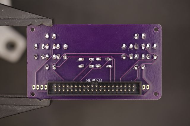
Here's what the soldered gamepad will look like. Clean and Shiny!
Crédit: AdaFruit Industries www.adafruit.com
Tap Gamepad PCB Mounting Holes
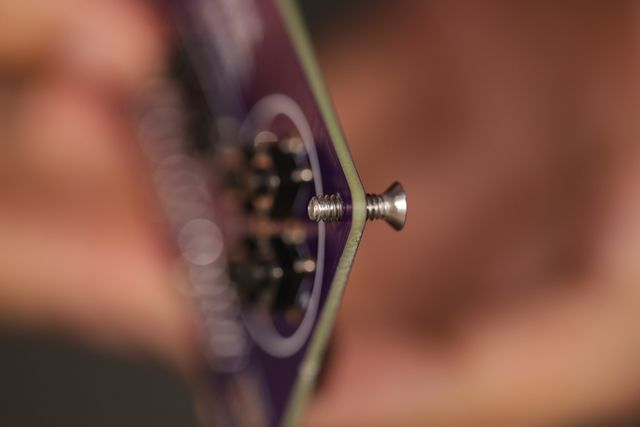
Now is a good time to tap the mounting holes of the gamepad PCB. We need to create threads on each hole so that it's easier to mount to the case. You can use a #4-40 sized tap tool, or a #4-40 machine screw to do this, just make sure to fasten as straight as you can.
Source: PiGRRL 2 - Make a portable Raspberry Pi 2 game console
Créé par les frères Ruiz pour AdaFruit Industries.
Traduction réalisée par Wrotny A pour MCHobby.be.
Toute référence, mention ou extrait de cette traduction doit être explicitement accompagné du texte suivant : « Traduction par MCHobby (www.MCHobby.be) - Vente de kit et composants » avec un lien vers la source (donc cette page) et ce quelque soit le média utilisé.
L'utilisation commercial de la traduction (texte) et/ou réalisation, même partielle, pourrait être soumis à redevance. Dans tous les cas de figures, vous devez également obtenir l'accord du(des) détenteur initial des droits. Celui de MC Hobby s'arrêtant au travail de traduction proprement dit.
Traduit avec l'autorisation d'AdaFruit Industries - Translated with the permission from Adafruit Industries - www.adafruit.com
