Rasp-PiGRRL-2-Montage
|
|
En cours de traduction/élaboration. |
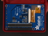
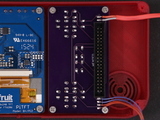
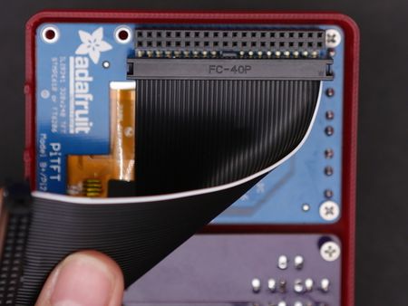
Placer le PiTFT
Crédit: AdaFruit Industries www.adafruit.com
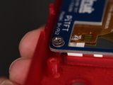
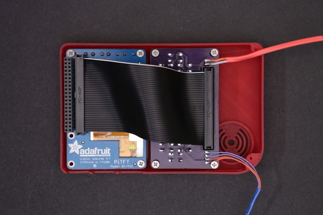
Connected PiTFT and Gamepad
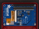
Now our PiTFT display and Gamepad PCB are mounted to the case. Press the buttons on the PiTFT and Gamepad to test them and see they feel good. If the buttons get stuck, the gamepad isn't flush with the standoffs.
Crédit: AdaFruit Industries www.adafruit.com
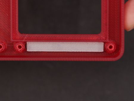
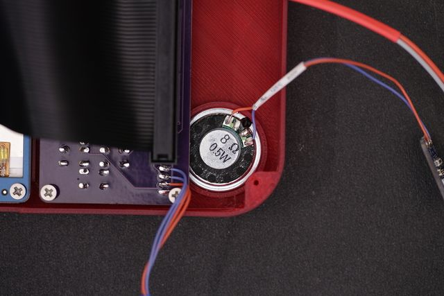
Installer le Haut-Parleur
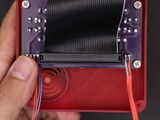
C'est le moment de placer le haut-parleur dans le boîtier. Placez le haut-parleur dans la cavité avec la grille et pressez le pour qu'il prenne place dans sont emplacement. Les fils doivent être orientés de sorte qu'ils ne viennent pas se prendre dans les supports.
|
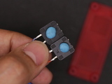
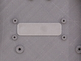
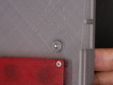
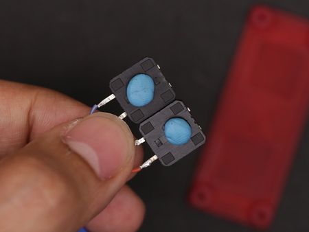
Ensuite, nous allons monter les deux boutons de l'arrière du boîtier (les boutons Shouder). Pour réaliser cette opération, nous aurons besoin de pâte adhésive ou de colle chaude - mais cela fonctionne également également avec de la pâte de montage (qui permet en plus de pouvoir ajuster la position des boutons).
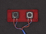
Placer la pâte (ou colle chaude) à l'arrière des boutons 12mm et positionnez les au dessus des deux emplacements carrés. d position them over the two recessed square spots on the mounting part. Press them down to stick them into place. |
|
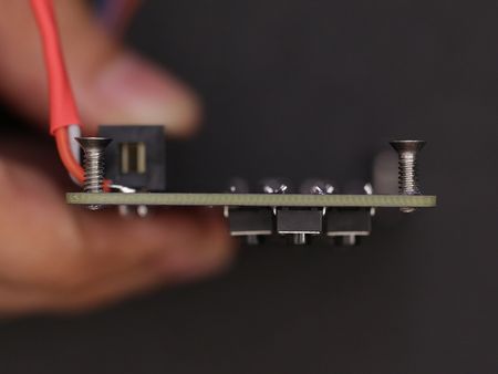
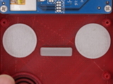
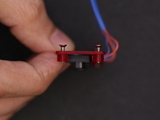
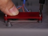
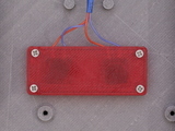
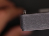
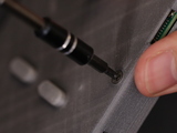
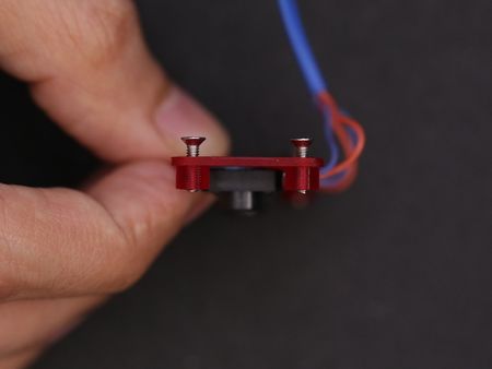
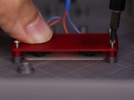
Fasten four #2-56 3/8 into the standoffs of the shoulder mount. Screw them in until the barely protrude the standoff - this is going to make it easier to mount it to the case. Next, insert the rubber shoulder button actuator into the cutout of the bottom case part. |
|
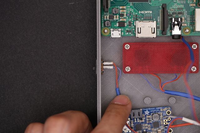
Place the shoulder mount over the standoffs on the bottom case. Make sure the screws line up with the standoffs - they're position / orientation specific. Once they're lined up, carefully fasten the screws down. Here, you can fasten them all the way. |
Crédit: AdaFruit Industries www.adafruit.com
Install Switch
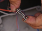
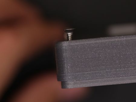
Now if a good time to insert the slide switch into the bottom case. Take note of the OFF position of the slide and install it to your liking (I prefer down is OFF, up is ON).
|
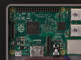
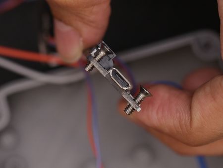
Next up, lets mount the Pi to the bottom case. First, let's fasten #4-40 3/8 sized machine screws to the two mount holes on the back of the bottom case part. Like the previous mounting standoffs, fasten the screws so they're just barely protuding through the top of the standoffs. Then, lay the Pi over the standoffs and line up the screws with the mounting holes. Once in place, fasten the screws all the way until they're flush with the surface of the case. |
|
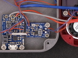
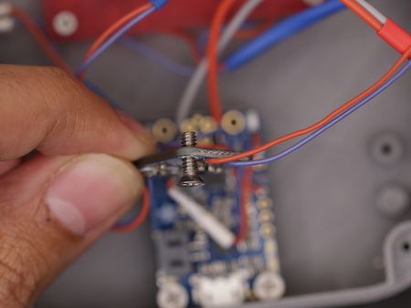
We'll need two #4-40 3/8 machine screws to install the PowerBoost to the case. Fasten the screws to the two mounting holes of the PowerBoost - This will create threads. Once they're made, lay the PowerBoost over the standoffs (close to the center bottom). Hold the PCB in place while fastening the screws to the standoffs. Don't fasten these screws all the way through, just deep enough they go past the heigh of the case - similar to the other components. |
|
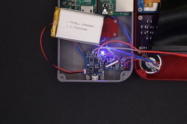
Insert and fasten a single #4-40 3/8 machine screw into the mounting hole of the amp PCB (should be the hole closest to the Adafruit logo) - This will help create the screw threads. Then, place the PCB over the standoffs and hole it down to fasten the screw into the standoff. |
Crédit: AdaFruit Industries www.adafruit.com
Test PowerBoost Circuit
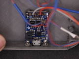
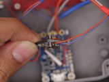
Grab the lipo battery and plug in the JST connector to the JST port on the PowerBoost 1000C. Flip the slide switch on, and see if the circuit works! The blue LED indicates the battery is charged and the circuit is powered on.
If the LED doesn't light up, you either have a defective PowerBoost, or a short. You'll have to double check your wiring for short using a a multi-meter. If you have any issues or questions, please post it on support forums at <a href="http://forums.adafruit.com/">http://forums.adafruit.com/</a>
Crédit: AdaFruit Industries www.adafruit.com
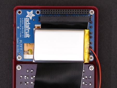
|
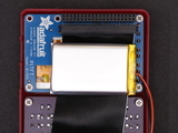
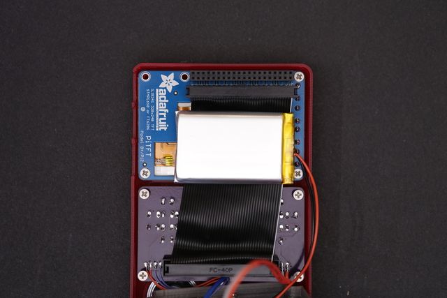
Now we can install the 2000mAh lipo battery. A good spot for it is right behind the PiTFT display. To keep it in place, we can use a piece of gaffers tape. Try to keep it up closely against PiCable. Position it like in the photo, closer to the right side to avoid intersecting with some of the components from the Pi. |
Almost Done!
In the next page, we'll close up the case and finish the build!
Source: PiGRRL 2 - Make a portable Raspberry Pi 2 game console
Créé par les frères Ruiz pour AdaFruit Industries.
Traduction réalisée par Wrotny A pour MCHobby.be.
Toute référence, mention ou extrait de cette traduction doit être explicitement accompagné du texte suivant : « Traduction par MCHobby (www.MCHobby.be) - Vente de kit et composants » avec un lien vers la source (donc cette page) et ce quelque soit le média utilisé.
L'utilisation commercial de la traduction (texte) et/ou réalisation, même partielle, pourrait être soumis à redevance. Dans tous les cas de figures, vous devez également obtenir l'accord du(des) détenteur initial des droits. Celui de MC Hobby s'arrêtant au travail de traduction proprement dit.
Traduit avec l'autorisation d'AdaFruit Industries - Translated with the permission from Adafruit Industries - www.adafruit.com
