Différences entre versions de « PowerBoost-500-Chargeur-Switch »
| Ligne 29 : | Ligne 29 : | ||
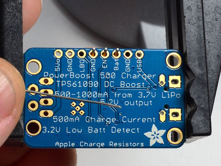
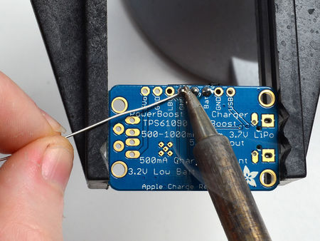
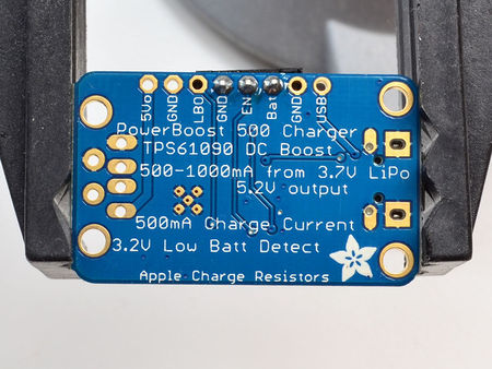
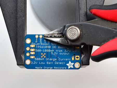
{{asm-text}} Clip off the long pins with diagonal cutters | {{asm-text}} Clip off the long pins with diagonal cutters | ||
| − | {{asm-row|img=PowerBoost-500-Chargeur-Switch- | + | {{asm-row|img=PowerBoost-500-Chargeur-Switch-15.jpg}} |
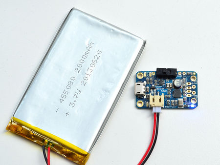
{{asm-text}} When the switch is to the left, the 5V power will be on, you can tell because the blue LED is lit | {{asm-text}} When the switch is to the left, the 5V power will be on, you can tell because the blue LED is lit | ||
| − | {{asm-row|img=PowerBoost-500-Chargeur-Switch- | + | {{asm-row|img=PowerBoost-500-Chargeur-Switch-16.jpg}} |
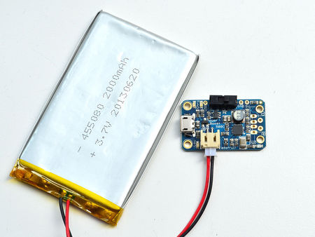
{{asm-text}} Slide to the right to turn it off. | {{asm-text}} Slide to the right to turn it off. | ||
Version du 6 décembre 2014 à 19:43
Interrupteur On/Off
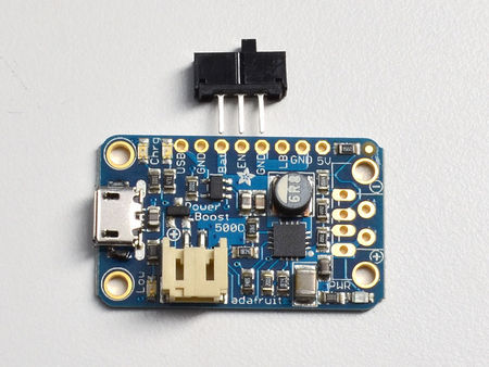
The PowerBoost 500C does not come with an on/off switch for the output, but its very easy to add one! Just grab a Breadboard friendly SPDT slide switch.
We will be turning the boost on/off via the ENABLE pin, so the switch does not have to carry any power, it is only signalling to the boost converter what to do. This means the switch can be small. Use any switch you like, if it is 0.1" spacing thats ideal. If your switch only has two pins instead of three, tie one pin to GND and the other pin to EN - when the switch is closed, the power will turn off.
Modèle:PowerBoost-500-Chargeur-Switch-01.jpg
Assembler
Crédit à AdaFruit.com pour toutes les images ci-dessous - All images here under are credited to AdaFruit.com
Tutoriel Adafruit PowerBoost 500 Charger créé par Lady Ada pour AdaFruit Industries.
Tutoriel traduit par Meurisse D. pour MCHobby.be
Traduit avec l'autorisation d'AdaFruit Industries - Translated with the permission from Adafruit Industries - www.adafruit.com
Toute référence, mention ou extrait de cette traduction doit être explicitement accompagné du texte suivant : « Traduction par MCHobby (www.MCHobby.be) - Vente de kit et composants » avec un lien vers la source (donc cette page) et ce quelque soit le média utilisé.
L'utilisation commercial de la traduction (texte) et/ou réalisation, même partielle, pourrait être soumis à redevance. Dans tous les cas de figures, vous devez également obtenir l'accord du(des) détenteur initial des droits. Celui de MC Hobby s'arrêtant au travail de traduction proprement dit.
