Différences entre versions de « Rasp-Retro-Games-Arcade-Control »
| Ligne 44 : | Ligne 44 : | ||
{{ADFImage|Rasp-Retro-Games-Arcade-Control-11.png}} | {{ADFImage|Rasp-Retro-Games-Arcade-Control-11.png}} | ||
| − | Notez que les broches GPIO 14 et 15 sont | + | Notez que les broches GPIO 14 et 15 sont hors sujet et interdite d'utilisation. Par défaut, elles sont configurées comme port série. Il est possible de désactiver le port série (pour récupérer les broches) mais cela nécessite de modifier la configuration de votre Pi (c'est un peu ennuyant, pas nécessaire puisque nous de nombreuses broches et surtout plus facile). |
| − | + | Les cartes de révision 2 dispose de 4 broches GPIO complémentaires (28–31) sur un connecteur adjacent mais cela nécessite quelques opérations de soudure. Si vous avez désespérément besoin d'entrées supplémentaires, vous trouverez des information sur [http://elinux.org/RPi_Low-level_peripherals Embedded Linux Wiki] (réservé aux utilisateurs avancés). | |
There are only five ground pins available on the header, but some gamers will need more controls than that. One of our {{pl|223|medium Perma-Proto boards}} can be used to provide a single large “ground rail” where one side of all the buttons can be connected. Alternately, if you have extra unused GPIO pins and just need a couple extra ground connections, we’ll show a software work-around for this. | There are only five ground pins available on the header, but some gamers will need more controls than that. One of our {{pl|223|medium Perma-Proto boards}} can be used to provide a single large “ground rail” where one side of all the buttons can be connected. Alternately, if you have extra unused GPIO pins and just need a couple extra ground connections, we’ll show a software work-around for this. | ||
Version du 16 mars 2014 à 21:07
Ajouter un controleur d'Arcade
Si vous êtes arrivé ici, vous disposez d'un (ou plusieurs) jeux auquel vous pouvez jouer au clavier. La prochaine étape consiste à ajouter les contrôles d'Arcade...
C'est maintenant que les choses prennent un tournant créatif. Il n'existe pas une disposition idéale des contrôles (manette et boutons) qui puisse convenir à tous les jeux. Par contre il existe quelques dispositions plus fréquentes qui conviennent à de nombreux cas. Et pour le reste, vous pouvez encore utiliser un clavier.
Vous aurez également besoin de réaliser votre panneau de commande en utilisant les matérieux et outils correspondant au mieux à vos compétences. Chez AdaFruit, nous avons la chance de pouvoir utiliser une découpeuse laser qui fonctionne avec de l’acrylique (plexyglass) mais cela resterait un défi de taille pour la plupart des gens. Du contreplaqué ou boite métallique sont des matériaux viable (une grande boite à cigare peut aussi convenir) pour faire les trous, vous pouvez utiliser une foreuse, une scie a trou, une Dremel ou une lime à bois. n'hésitez pas improviser!
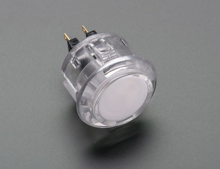
Si vous ne disposez pas d'un fournisseur de bouton sous la main, sachez que MCHobby propose aussi un joli assortiment de bouton d'arcade:
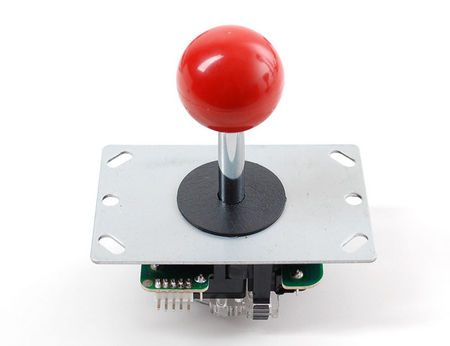
Les éléments
Crédit pour les images ci-dessous à AdaFruit Industries - All images here under are credited to AdaFruit Industries
Le joystick d'un ordinateur Atari ou Commodore peut aussi être utilisé. Les joysticks des consoles plus récentes utilise un protocole série... et malheureusement, cela ne fonctionnera pas ici. Les gamepads USB est une autre option viable.
| Nous proposons des contrôles d'arcade sur le WebShop de MCHobby, contrôles qui doivent être montés. N'oubliez pas que forer et couper sont des opérations à réaliser avec un minimum de précaution et règles de bon sens comme utiliser DES LUNETTES DE SECURITE et couper VERS L'EXTERIEUR (jamais vers soi), porter des vêtements adaptés, etc. |
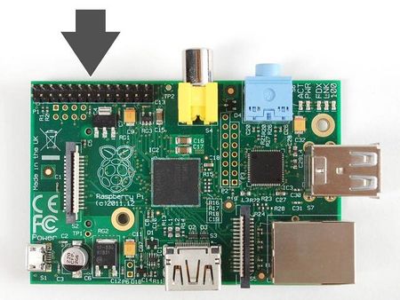
Broches du GPIO
Chaque broche du connecteur dispose d'un "numéro GPIO" unique qui diffère de l'ordre des broches sur le connecteur. Les boutons et joystick (chacun ayant 4 directions) seront connectés parmi les différentes broches GPIO disponible et la masse (GND).
La plupart des cartes Raspberry Pi suivent maintenant l'arrangement des broches de la "Revision 2":
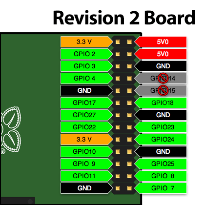
Crédit: AdaFruit Industries www.adafruit.com
Si vous disposez toujours d'un ancien modèle (prédécesseur de la carte Modèle B) est facile à reconnaitre car elle n'a pas de trou de montage. Dans ce cas le numéro des broches est différent:
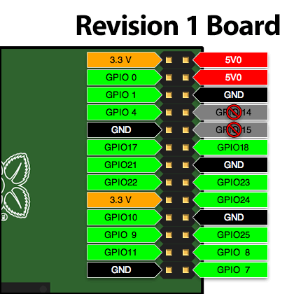
Crédit: AdaFruit Industries www.adafruit.com
Notez que les broches GPIO 14 et 15 sont hors sujet et interdite d'utilisation. Par défaut, elles sont configurées comme port série. Il est possible de désactiver le port série (pour récupérer les broches) mais cela nécessite de modifier la configuration de votre Pi (c'est un peu ennuyant, pas nécessaire puisque nous de nombreuses broches et surtout plus facile).
Les cartes de révision 2 dispose de 4 broches GPIO complémentaires (28–31) sur un connecteur adjacent mais cela nécessite quelques opérations de soudure. Si vous avez désespérément besoin d'entrées supplémentaires, vous trouverez des information sur Embedded Linux Wiki (réservé aux utilisateurs avancés).
There are only five ground pins available on the header, but some gamers will need more controls than that. One of our medium Perma-Proto boards can be used to provide a single large “ground rail” where one side of all the buttons can be connected. Alternately, if you have extra unused GPIO pins and just need a couple extra ground connections, we’ll show a software work-around for this.
The processor in the Raspberry Pi has the ability to turn on 'internal' pullups so you do not need external pull-up resistors for the buttons or arcade controller
Just as the layout and build technique of the control panel requires creative interpretation, so too will you need to decide on your own wiring methodology. We have some parts that can help. Aside from the aforementioned Perma-Proto board, there are quick-connect wires that work with the buttons and assortiment de fil de connexion multifonctionnel in various lengths that can be used with a joystick or plug directly into the GPIO pins (without a Perma-Proto board). Options abound! You’ll likely need some combination of these, and may need to solder some connections.
Raccordement
Le joystick
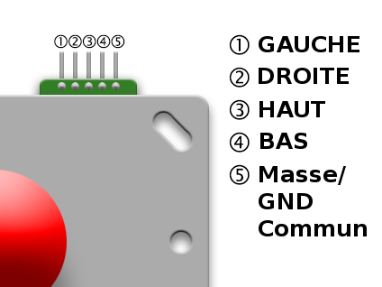
Crédit: AdaFruit Industries www.adafruit.com
Here’s a pinout diagram for our arcade stick. Only one wire needs to go to GND, then each of the other four goes to a different GPIO pin.
These directions apply when the stick is oriented with the header at the top. It’s fine to install the stick in a different orientation, you’ll just need to adapt the wiring connections to match.
Raccordement sur le GPIO
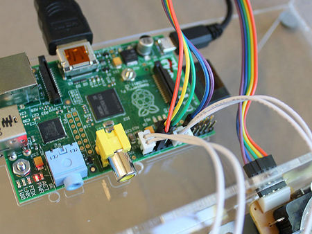
The plugs on the ends of the Quick Connect Wires tend to block adjacent pins on the GPIO header. You can trim these down a bit using an X-Acto knife or Dremel tool, or cut the plugs off and solder the wires to a Perma Proto board, or simply plan out your wiring to avoid nearby pins.
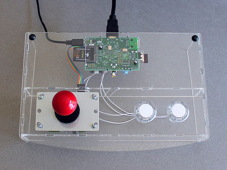
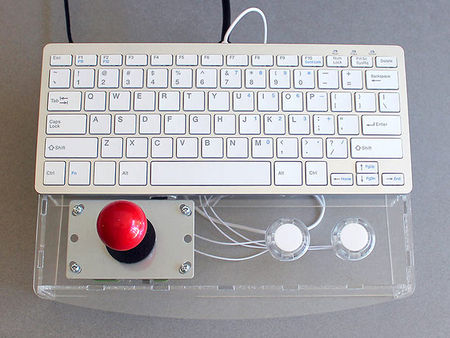
Here’s a no-soldering wiring setup we use with one joystick and two buttons, using 5 female-to-female jumpers for the joystick and two unmodified quick connects for the buttons. It’s a pretty basic layout, but sufficient to accommodate quite a few classic games. For the remaining seldom-used functions (coin insert, start game), a regular USB keyboard is kept nearby.
If you dont mind doing some soldering, you can connect to the other pins - just make sure one pin of each button connects to a GPIO and the other button pin connects to one of the ground pins. You may need to edit/recompile our 'helper'
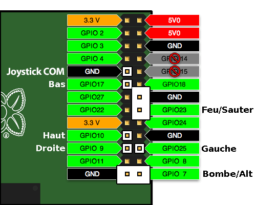
Crédit: AdaFruit Industries www.adafruit.com
Un dernier élément
Our “retrogame” utility is the software glue that joins these keyboard-driven games to our GPIO-connected controls.
Download retrogame from GitHub. Select the “download ZIP” button and uncompress this file on your Raspberry Pi.
A pre-built version of retrogame is included in the ZIP file. If using the joystick and button layout described above, this program can be used as-is. Otherwise, the C source code needs some editing, and you’ll need to compile it (a Makefile is provided) after making changes. The GPIO pin to keyboard remapping is currently handled with a table in the source…this should be edited to match your unique wiring setup.
cd Adafruit-Retrogame
nano retrogame.c
(Of course you can substitute your editor of preference there — “nano” is easier for beginners.)
Starting around line 77 you’ll see a table resembling this:
struct {
        int pin;
        int key;
} io[] = {
//        Input    Output (from /usr/include/linux/input.h)
        { 25,      KEY_LEFT     },
        {  9,      KEY_RIGHT    },
        { 10,      KEY_UP       },
        { 17,      KEY_DOWN     },
        { 23,      KEY_LEFTCTRL },
        {  7,      KEY_LEFTALT  }
};
Each line in this table contains two elements. The first is a GPIO pin number (where a button or one direction from a joystick is attached), the second is the corresponding key code to be generated by this control. A list of valid key code names can be found in the file /usr/include/linux/input.h starting around line 178. Remember to enclose each pin/key pair in {curly braces} with a comma between them.
By default, the code is set up to match our example “no solder” controller wiring. This also works directly with the standard MAME controls. So you might not need to change anything; the pre-built version may have you covered.
If you need an extra ground pin (and have extra GPIO pins available that you’re not using for controls), set the key code to GND instead.
Write your changes to the file and exit the editor, then type:
make
This should build the executable retrogame utility. If you instead get an error message, there’s a problem in the edited table — most likely a missing curly brace, comma or semicolon.
But wait...we’re not ready to run yet! Retrogame requires the uinput kernel module. This is already present on the system but isn’t enabled by default. For testing, you can type:
sudo modprobe uinput
To make this persistent between reboots, append a line to /etc/modules:
sudo sh -c 'echo uinput >> /etc/modules'
Now we’re in good shape to test it!
Retrogame needs to be run as root, i.e.:
sudo ./retrogame
Give it a try. If it seems to be working, press control+C to stop the program and we’ll then set up the system to launch this automatically in the background at startup.
sudo nano /etc/rc.local
Before the final “exit 0” line, insert this line:
/home/pi/Adafruit-Retrogame/retrogame &
If you placed the software in a different location, this line should be changed accordingly. “sudo” isn’t necessary here because the rc.local script is already run as root.
Reboot the system to test the startup function:
sudo reboot
The software will now be patiently waiting in the background, ready for use with any emulators.
Each emulator will have its own method for configuring keyboard input. Set them up so the keys match your controller outputs. Up/down/left/right from the arrow keys is a pretty common default among these programs, but the rest will usually require some tweaking.
Source: Adafruit Retro Gaming with Raspberry Pi
Créé par Phillip Burgess pour AdaFruit Industries.
Traduction réalisée par Meurisse D pour MCHobby.be.
Toute référence, mention ou extrait de cette traduction doit être explicitement accompagné du texte suivant : « Traduction par MCHobby (www.MCHobby.be) - Vente de kit et composants » avec un lien vers la source (donc cette page) et ce quelque soit le média utilisé.
L'utilisation commercial de la traduction (texte) et/ou réalisation, même partielle, pourrait être soumis à redevance. Dans tous les cas de figures, vous devez également obtenir l'accord du(des) détenteur initial des droits. Celui de MC Hobby s'arrêtant au travail de traduction proprement dit.
Traduit avec l'autorisation d'AdaFruit Industries - Translated with the permission from Adafruit Industries - www.adafruit.com
