Tutoriel Librairie Adafruit GFX
|
|
En cours de traduction |
Librarie AdaFruit GFX
Introduction text
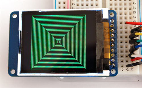
La librairie Adafruit_GFX pour Arduino fournit une syntaxe commune et un ensemble de fonction graphique pour tous les affichages LCD et OLED d'AdaFruit. Cela permet d'adapter facilement vos sketchs Arduino d'un afficheur à l'autre avec un minimum de modification. L'autre avantage est que toute les nouvelles fonctionnalités, amélioration de performance ou bug fix sont immédiatement disponible au travers de toute l'offre AdaFruit (tous les afficheurs).
La librairie Adafruit_GFX fonctionne avec une seconde librairies qui fournit des services de base pour un écran spécifique — par exemple, pour l'écran LCD ST7735 1.8" couleur, il faut installer la librairie Adafruit_GFX et la librairie Adafruit_ST7735. Ce principe reste identique pour tous les écrans AdaFruit... voir la liste ci-dessous:
Produits disponibles
Les produits ci-dessous sont disponibles (en stock) chez MC Hobby. Pensez à visiter notre WebShop... la liste ci-dessous n'est peut être pas encore à-jour ;-)
- Adafruit_TFTLCD, pour l'écran tactile 2.8" TFT pour Arduino, un shield AdaFruit.
Produits disponibles sur commande
Produit que MC Hobby importe sur demande.
Si vous désirez l'un de ces produits, envoyez un e-mail à info (arobase) mchobby.be:
- Adafruit_TFTLCD, Pour le breakout board Ecran Tactile 2.8" 2.8" TFT LCD touchscreen d'AdaFruit.
- RGBmatrixPanel, pour l'affichage à Matrice LED RGB 16x32 et 32x32 d'AdaFruit (RGB LED Matrix panels).
- Adafruit_HX8340B, pour le 2.2" TFT Display with microSD d'AdaFruit.
- Adafruit_ST7735, pour le 1.8" TFT Display with microSD d'AdaFruit.
- Adafruit_PCD8544, pour l'écran LCD Nokia 5110/3310 monochrome.
- Adafruit-Graphic-VFD-Display-Library, pour l'écran graphique VFD 128x64 d'AdaFruit.
- Adafruit-SSD1331-OLED-Driver-Library-for-Arduino pour l'écran OLED couleur 16 bits de 0.96" w/microSD d'AdaFruit.
- Adafruit_SSD1306 pour l'écran OLEDs Monochrome 128x64 et OLEDs Monochrome 128x32 d'AdaFruit.
Les librairies sont écrites en C++ pour Arduino mais peuvent être facilement portée vers n'importe quel microcontrôleur en ré-écrivant les fonctions de bas-niveau contrôlant les broches/pins.
Coordonnées système et unités
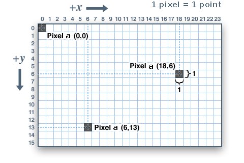
Pixels — picture elements, the blocks comprising a digital image — are addressed by their horizontal (X) and vertical (Y) coordinates. The coordinate system places the origin (0,0) at the top left corner, with positive X increasing to the right and positive Y increasing downward. This is upside-down relative to the standard Cartesian coordinate system of mathematics, but is established practice in many computer graphics systems (a throwback to the days of raster-scan CRT graphics, which worked top-to-bottom). To use a tall “portrait” layout rather than wide “landscape” format, or if physical constraints dictate the orientation of a display in an enclosure, one of four rotation settings can also be applied, indicating which corner of the display represents the top left.
Also unlike the mathematical Cartesian coordinate system, points here have dimension — they are always one full integer pixel wide and tall.
Coordinates are always expressed in pixel units; there is no implicit scale to a real-world measure like millimeters or inches, and the size of a displayed graphic will be a function of that specific display’s dot pitch or pixel density. If you’re aiming for a real-world dimension, you’ll need to scale your coordinates to suit. Dot pitch can often be found in the device datasheet, or by measuring the screen width and dividing the number of pixels across by this measurement.
For color-capable displays, colors are represented as unsigned 16-bit values. Some displays may physically be capable of more or fewer bits than this, but the library operates with 16-bit values…these are easy for the Arduino to work with while also providing a consistent data type across all the different displays. The primary color components — red, green and blue — are all “packed” into a single 16-bit variable, with the most significant 5 bits conveying red, middle 6 bits conveying green, and least significant 5 bits conveying blue. That extra bit is assigned to green because our eyes are most sensitive to green light. Science!
For the most common primary and secondary colors, we have this handy cheat-sheet that you can include in your own code. Of course, you can pick any of 65,536 different colors, but this basic list may be easiest when starting out:
// définition des couleurs (mot clé en anglais)
#define BLACK    0x0000 // noir
#define BLUE     0x001F // Bleu
#define RED      0xF800 // Rouge
#define GREEN    0x07E0 // Vert
#define CYAN     0x07FF // Cyan
#define MAGENTA  0xF81F // Magenta
#define YELLOW   0xFFE0 // Jaune
#define WHITE    0xFFFF // Blanc
For monochrome (single-color) displays, colors are always specified as simply 1 (set) or 0 (clear). The semantics of set/clear are specific to the type of display: with something like a luminous OLED display, a “set” pixel is lighted, whereas with a reflective LCD display, a “set” pixel is typically dark. There may be exceptions, but generally you can count on 0 (clear) representing the default background state for a freshly-initialized display, whatever that works out to be.
Primitives graphiques
Each device-specific display library will have its own constructors and initialization functions. These are documented in the individual tutorials for each display type, or oftentimes are evident in the specific library header file. The remainder of this tutorial covers the common graphics functions that work the same regardless of the display type.
The function descriptions below are merely prototypes — there’s an assumption that a display object is declared and initialized as needed by the device-specific library. Look at the example code with each library to see it in actual use. For example, where we show print(1234.56), your actual code would place the object name before this, e.g. it might read screen.print(1234.56) (if you have declared your display object with the name screen).
Dessiner des pixels (points)
First up is the most basic pixel pusher. You can call this with X, Y coordinates and a color and it will make a single dot:
void drawPixel(uint16_t x, uint16_t y, uint16_t color);
Dessiner une ligne
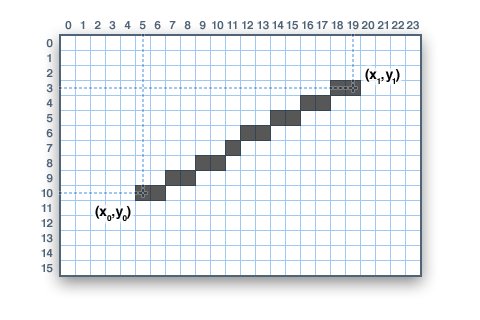
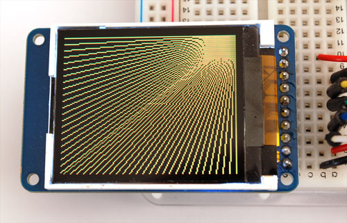
You can also draw lines, with a starting and end point and color:
void drawLine(uint16_t x0, uint16_t y0, uint16_t x1, uint16_t y1, uint16_t color);
For horizontal or vertical lines, there are optimized line-drawing functions that avoid the angular calculations:
void drawFastVLine(uint16_t x0, uint16_t y0, uint16_t length, uint16_t color);
void drawFastHLine(uin86_t x0, uin86_t y0, uint8_t length, uint16_t color);
Dessiner un rectangle
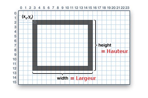
Next up, rectangles and squares can be drawn and filled using the following procedures. Each accepts an X, Y pair for the top-left corner of the rectangle, a width and height (in pixels), and a color. drawRect() renders just the frame (outline) of the rectangle — the interior is unaffected — while fillRect() fills the entire area with a given color:
void drawRect(uint16_t x0, uint16_t y0, uint16_t w, uint16_t h, uint16_t color);
void fillRect(uint16_t x0, uint16_t y0, uint16_t w, uint16_t h, uint16_t color);
To create a solid rectangle with a contrasting outline, use fillRect() first, then drawRect() over it.
Dessiner des cercles
Références
- Source: Cet Article
Toute référence, mention ou extrait de cette traduction doit être explicitement accompagné du texte suivant : « Traduction par MCHobby (www.MCHobby.be) - Vente de kit et composants » avec un lien vers la source (donc cette page) et ce quelque soit le média utilisé.
L'utilisation commercial de la traduction (texte) et/ou réalisation, même partielle, pourrait être soumis à redevance. Dans tous les cas de figures, vous devez également obtenir l'accord du(des) détenteur initial des droits. Celui de MC Hobby s'arrêtant au travail de traduction proprement dit.
Traduit avec l'autorisation d'AdaFruit Industries - Translated with the permission from Adafruit Industries - www.adafruit.com
