Différences entre versions de « ADF-RTC-DS1307-SOUDER »
| Ligne 7 : | Ligne 7 : | ||
[[Fichier:ADF-RTC-DS1307-BUILD-00.jpg]] | [[Fichier:ADF-RTC-DS1307-BUILD-00.jpg]] | ||
| − | Ensuite, Chauffez votre {{iron}} et nettoyer votre bureau. | + | Ensuite, Chauffez votre {{link-product-iron}} et nettoyer votre bureau. |
| − | Placez la carte du circuit sur un {{vise}} de façon a pouvoir travailler plus facilement. | + | Placez la carte du circuit sur un {{link-product-vise}} de façon a pouvoir travailler plus facilement. |
[[Fichier:ADF-RTC-DS1307-BUILD-01.jpg]] | [[Fichier:ADF-RTC-DS1307-BUILD-01.jpg]] | ||
Version du 21 janvier 2013 à 07:15
Voici les notes qui vous guiderons étape par étape dans l'assemblage du kit.
Préparez vous à assembler ce kit en commençant par vérifier la liste des pièces et tout est bien à disposition!
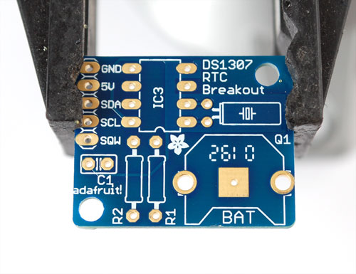
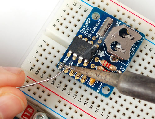
Ensuite, Chauffez votre fer à souder et nettoyer votre bureau.
Placez la carte du circuit sur un étau 3ieme main de façon a pouvoir travailler plus facilement.
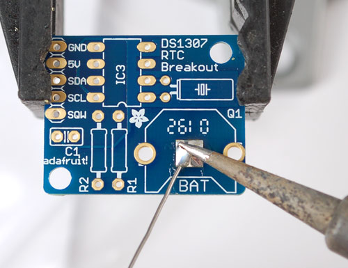
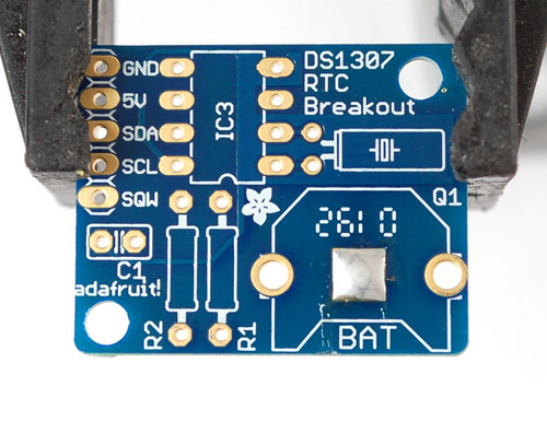
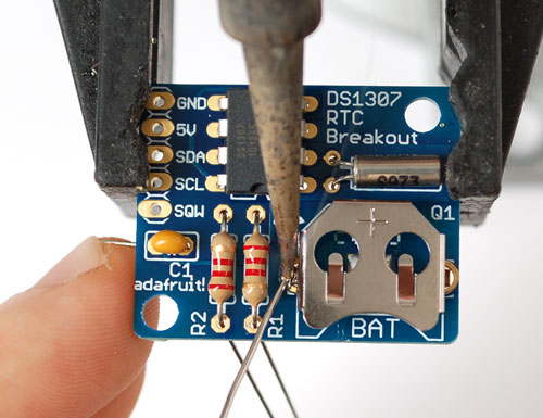
Begin by soldering a small bump onto the negative pad of the battery: this will make better contact!
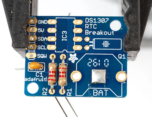
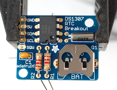
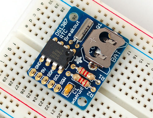
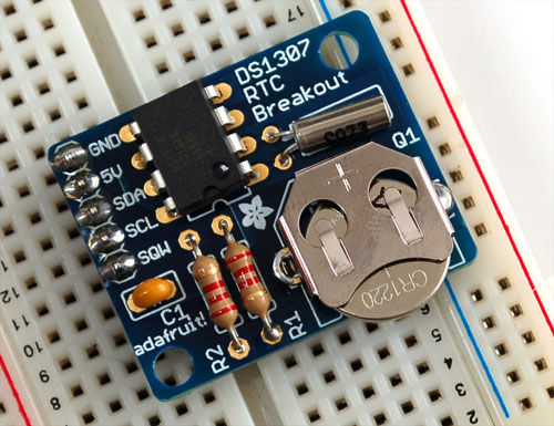
place the two 2.2K resistors, and the ceramic capacitor. They are symmetric so no need to worry about direction.
Then place the crystal (also symmetric), the battery holder (goes on so that the battery can slip in the side) and the RTC chip.
The RTC chip must be placed so that the notch/dot on the end match the silkscreen. Look at the photo on the left, the notch is pointing down. Double check this before soldering in the chip because its quite hard to undo!
To keep the battery holder from falling out, you may want to 'tack' solder it from the top
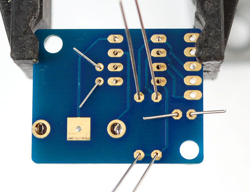
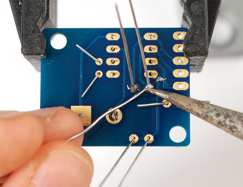
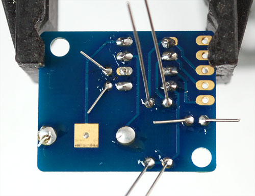
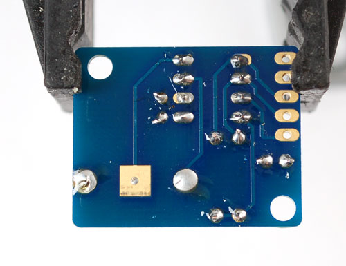
Then flip over the board and solder all the pins.
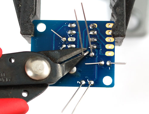
Clip the leads of the resistors, crystal and capacitor short.
If you'd like to use the header to plug the breakout board into something, place the header in a breadboard, long side down and place the board so that the short pins stick thru the pads.
Solder them in place.
Insert the battery so that the flat + side is UP.
The battery will last for many years, 5 or more, so no need to ever remove or replace it.
You MUST have a coin cell installed for the RTC to work, if there is no coin cell, it will act strangly and possibly hang the Arduino so ALWAYS make SURE there's a battery installed, even if its a dead battery.
Source: DS1307 Real Time Clock Breakout Board Kit. Ecrit par Tyler Cooper pour AdaFruit. Crédit AdaFruit Industries
Traduit par Meurisse D. pour MCHobby.be
Traduit avec l'autorisation d'AdaFruit Industries - Translated with the permission from Adafruit Industries - www.adafruit.com
Toute référence, mention ou extrait de cette traduction doit être explicitement accompagné du texte suivant : « Traduction par MCHobby (www.MCHobby.be) - Vente de kit et composants » avec un lien vers la source (donc cette page) et ce quelque soit le média utilisé.
L'utilisation commercial de la traduction (texte) et/ou réalisation, même partielle, pourrait être soumis à redevance. Dans tous les cas de figures, vous devez également obtenir l'accord du(des) détenteur initial des droits. Celui de MC Hobby s'arrêtant au travail de traduction proprement dit.
