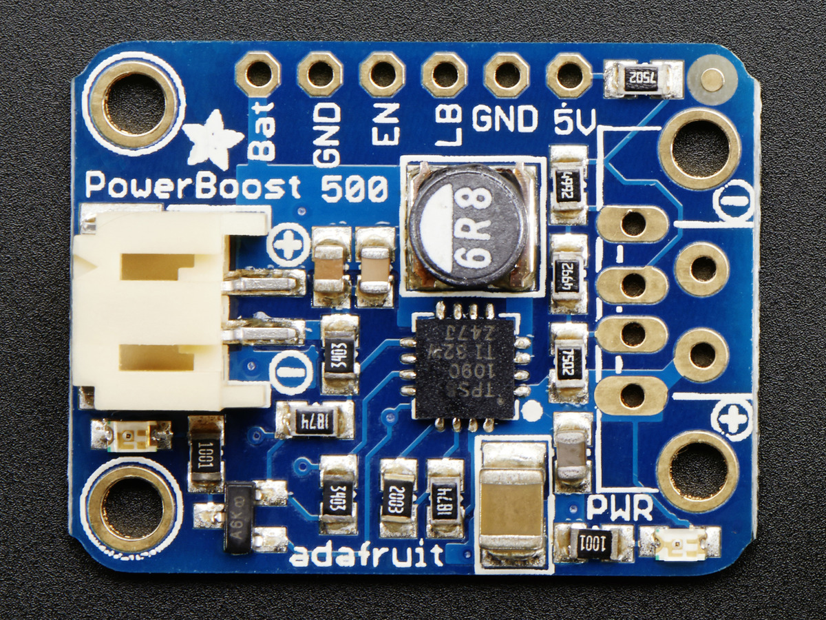
PowerBoost-500-Basic-PinOut
For many people, the PowerBoost can be used with just the power input and power outputs. However, we have a couple handy breakouts so lets get started!

Crédit: AdaFruit Industries www.adafruit.com
Broches d'alimentation
There's two power 'ports' - an input (called BAT) and an output (called 5V)
- BAT - this is the battery input, it can range from 1.8V to 5V. Higher voltages will let you draw more current and in general, are more efficient. Try to keep the wires going to this pin nice and short - 3" or less is best!
- GND - this is the power ground. This boost converter is not 'isolated' - the ground input is the same as the ground output
- 5V - this is the boosted output. When the board is running, the voltage will be 5.2V approximately. It may dip down to 5V as the current draw starts to go up (over 500mA). When the board is disabled, this output is 'floating' but you should still try not to apply a voltage to it while the board is disabled. There's a green LED connected to this pin which will let you know when there's power output
Broches de contrôle
There's two 'control' pins.
- EN - this is the 'enable' pin. By default it is pulled 'high' to VBAT. To turn off the booster, connect this pin to ground. The switch can be as small as you like, it is just a signal. Contrast this to an inline power switch which would have to be able to handle up to 2A of current! When the chip is disabled the output is completely disconnected from the input.
- LBO - not a leveraged buy out! this is the Low Battery Output. By default it is pulled high to BAT but when the charger detects a low voltage (under 3.2V) the pin will drop down to 0V. You can use this to signal when its time to shut down or alert the user that the battery is low. There is also a red LED connected to this pin.
Tutoriel Adafruit PowerBoost 500 Basic créé par Lady Ada pour AdaFruit Industries.
Tutoriel traduit par Meurisse D. pour MCHobby.be
Traduit avec l'autorisation d'AdaFruit Industries - Translated with the permission from Adafruit Industries - www.adafruit.com
Toute référence, mention ou extrait de cette traduction doit être explicitement accompagné du texte suivant : « Traduction par MCHobby (www.MCHobby.be) - Vente de kit et composants » avec un lien vers la source (donc cette page) et ce quelque soit le média utilisé.
L'utilisation commercial de la traduction (texte) et/ou réalisation, même partielle, pourrait être soumis à redevance. Dans tous les cas de figures, vous devez également obtenir l'accord du(des) détenteur initial des droits. Celui de MC Hobby s'arrêtant au travail de traduction proprement dit.