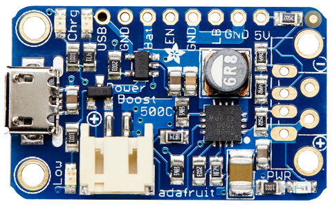
PowerBoost-500-Chargeur-PinOut
Brochage
Pour de nombreuses personnes, le PowerBoost 500 Chargeur peut être vu comme un accu rechargeable par microUSB et disposant d'une sortie alimentation USB. AdaFruit a cependant ajouté des breakouts bien utiles... voyons un peu ce qu'il y a sous le capot!

Crédit: AdaFruit Industries www.adafruit.com
Broches d'alimentation
Il y a trois points d'alimentation: L'entrée USB pour charger l'accu (4.75 à 5.25V, ce qui sort généralement d'un port USB), L'accu lui-même (3 à 4.2V) et la sortie (output) de 5 à 5.2V.
- USB: C'est la broche d'alimentation USB 5V. C'est la broche utilisée pour charger l'accu, PAS la sortie d'alimentation! Vous pouvez l'utiliser si vous avez besoin d'obtenir une source d'alimentation depuis la prise microUSB (lorsqu'elle est branchée). Bien pratique pour savoir si la microUSB est branchée (pour charger l'accu).
- GND: C'est la masse/Ground de l'alimentation. Le convertisseur BOOST n'est pas 'isolé' - la masse d'entrée et la masse de sortie sont commune (c'est la même)
- BAT: C'est l'entrée de l'accu, connecté directement sur une fiche JST. Pour la plupart des accu Lithium, la tension va de 3.0V pour un accu presque mort à 4.2V pour un accu pleinement chargé. D'une façon générale, plus la tension de l'accu est élevée et plus vous pouvez obtenir un courant (et le convertisseur est aussi plus efficace). Essayez de garder les fils de BAT le plus court possible (7cm ou mois, c'est l'idéal!).
- 5V: C'est la sortie Boostée. Lorsque la carte fonctionne, la tension de sortie sera approximativement de 5.2V. Cette tension chute à 5V lorsque le courant de sortie commence à devenir plus important (au dessus de 500mA). Lorsque la carte est désactivée, la sortie est 'flottante'. Bien que la sortie soit flottante dans ce cas, vous ne devriez pas y appliquer une tension.
Il y a une LED verte connectée sur cette broche qui indique que la sortie est active.
Broches de contrôle
There's two 'control' pins.
- EN: this is the 'enable' pin. By default it is pulled 'high' to VBAT. To turn off the booster, connect this pin to ground. The switch can be as small as you like, it is just a signal. Contrast this to an inline power switch which would have to be able to handle up to 2A of current! When the chip is disabled the output is completely disconnected from the input.
- LBO: not a leveraged buy out! this is the Low Battery Output. By default it is pulled high to BAT but when the charger detects a low voltage (under 3.2V) the pin will drop down to 0V. You can use this to signal when its time to shut down or alert the user that the battery is low. There is also a red LED connected to this pin.
Led LEDs
There are four onboard LEDs.
- The Blue LED sits next to the USB connector socket, and indicates the 5V output power state.
- The Red LED is next to the battery JST port and indicates when the battery voltage is below 3.2VDC (Low Battery Output)
- The Yellow LED is next to the microUSB connector and indicates when the battery is being charged
- The Green LED is also next to the microUSB connector and indicates when the battery is done charging (all full)
Connexion Accu et USB
You can connect a battery to the breakout strip or to the JST connector. All of Adafruit batteries come with JST cables that will plug in nicely so we strongly suggest that. Watch the polarity of the cable! the + and - markings next to the JST will let you know which way is which.
The USB connector can be soldered on to create a portable 'USB power pack'. The two data lines on USB have resistor dividers that match Apple charger values so that you can plug any iOS device in to charge. 99% of other phones, devices and tables are totally cool with these resistors as well. You can always short the D+ and D- lines if you happen to have a phone that wants shorted data lines.
If you don't want a USB connector attached, there are two holes that are designed for a 3.5mm spaced terminal block (not included)
Tutoriel Adafruit PowerBoost 500 Charger créé par Lady Ada pour AdaFruit Industries.
Tutoriel traduit par Meurisse D. pour MCHobby.be
Traduit avec l'autorisation d'AdaFruit Industries - Translated with the permission from Adafruit Industries - www.adafruit.com
Toute référence, mention ou extrait de cette traduction doit être explicitement accompagné du texte suivant : « Traduction par MCHobby (www.MCHobby.be) - Vente de kit et composants » avec un lien vers la source (donc cette page) et ce quelque soit le média utilisé.
L'utilisation commercial de la traduction (texte) et/ou réalisation, même partielle, pourrait être soumis à redevance. Dans tous les cas de figures, vous devez également obtenir l'accord du(des) détenteur initial des droits. Celui de MC Hobby s'arrêtant au travail de traduction proprement dit.