Différences entre versions de « Hack-ENG-MotorSkin-Presentation »
| Ligne 19 : | Ligne 19 : | ||
* '''In the complete kit''': An {{pl|561|HC-SR04 ultrasonic sensor}} used to evaluate distances and avoids obstacles. | * '''In the complete kit''': An {{pl|561|HC-SR04 ultrasonic sensor}} used to evaluate distances and avoids obstacles. | ||
| − | == | + | == Used pins == |
| − | + | To ease the usage of Pyboard pins, we did anotate the motor-skin with PyBoard pin names. | |
[[Fichier:MOTOR-SKIN-BOARD-v1.1-PIN-USED.jpg|320px]] | [[Fichier:MOTOR-SKIN-BOARD-v1.1-PIN-USED.jpg|320px]] | ||
| − | ''' | + | '''The pins used by the motor-skin are surrounded with parenthesis'''. |
{| class="wikitable" border="1" | {| class="wikitable" border="1" | ||
|- | |- | ||
| − | | align="center" | | + | | align="center" | PyBoard pin |
| − | | align="center" | Mode | + | | align="center" | Pin Mode |
| − | | align="center" | | + | | align="center" | Usage |
| − | | align="center" | | + | | align="center" | Details |
|- style="font-size: 90%" | |- style="font-size: 90%" | ||
| align="left" | X17 | | align="left" | X17 | ||
| align="left" | INPUT<br />''Internal PullUp'' | | align="left" | INPUT<br />''Internal PullUp'' | ||
| align="left" | SW1 | | align="left" | SW1 | ||
| − | | align="left" | | + | | align="left" | User button 1 (pin shorted to the ground when the pressing the button) |
|- style="font-size: 90%" | |- style="font-size: 90%" | ||
| align="left" | X18 | | align="left" | X18 | ||
| align="left" | INPUT<br />''Internal PullUp'' | | align="left" | INPUT<br />''Internal PullUp'' | ||
| align="left" | SW2 | | align="left" | SW2 | ||
| − | | align="left" | | + | | align="left" | User button 2 (pin shorted to the ground when the pressing the button) |
|- style="font-size: 90%" | |- style="font-size: 90%" | ||
| align="left" | X19 | | align="left" | X19 | ||
| align="left" | INPUT<br />''Internal PullUp'' | | align="left" | INPUT<br />''Internal PullUp'' | ||
| align="left" | SW3 | | align="left" | SW3 | ||
| − | | align="left" | | + | | align="left" | User button 3 (pin shorted to the ground when the pressing the button) |
|- style="font-size: 90%" | |- style="font-size: 90%" | ||
| align="left" | X20 | | align="left" | X20 | ||
| align="left" | INPUT<br />''Internal PullUp'' | | align="left" | INPUT<br />''Internal PullUp'' | ||
| align="left" | SW4 | | align="left" | SW4 | ||
| − | | align="left" | | + | | align="left" | User button 4 (pin shorted to the ground when the pressing the button) |
|- style="font-size: 90%" | |- style="font-size: 90%" | ||
| align="left" | Y5 | | align="left" | Y5 | ||
| align="left" | OUTPUT | | align="left" | OUTPUT | ||
| align="left" | HC-SR04 Trigger | | align="left" | HC-SR04 Trigger | ||
| − | | align="left" | | + | | align="left" | Trigger the ultrasonic sound to measure the distance |
|- style="font-size: 90%" | |- style="font-size: 90%" | ||
| align="left" | Y6 | | align="left" | Y6 | ||
| align="left" | INPUT | | align="left" | INPUT | ||
| align="left" | HC-SR04 Echo | | align="left" | HC-SR04 Echo | ||
| − | | align="left" | | + | | align="left" | Activated when the ultrasonic echo is received by the sensor |
|- style="font-size: 90%" | |- style="font-size: 90%" | ||
| align="left" | X6 | | align="left" | X6 | ||
| align="left" | OUTPUT | | align="left" | OUTPUT | ||
| − | | align="left" | | + | | align="left" | Motor 1 control |
| − | | align="left" | | + | | align="left" | First pin to control the H-Bridge of motor 1 |
|- style="font-size: 90%" | |- style="font-size: 90%" | ||
| align="left" | X5 | | align="left" | X5 | ||
| align="left" | OUTPUT | | align="left" | OUTPUT | ||
| − | | align="left" | | + | | align="left" | Motor 1 control |
| − | | align="left" | | + | | align="left" | Second pin to control the H-Bridge of motor 1 |
|- style="font-size: 90%" | |- style="font-size: 90%" | ||
| align="left" | X3 | | align="left" | X3 | ||
| align="left" | OUTPUT PWM<br />''Timer 5, Channel 3'' | | align="left" | OUTPUT PWM<br />''Timer 5, Channel 3'' | ||
| − | | align="left" | | + | | align="left" | Motor 1 speed control |
| − | | align="left" | | + | | align="left" | Enable pin of the motor 1 H-Bridge. |
|- style="font-size: 90%" | |- style="font-size: 90%" | ||
| align="left" | X7 | | align="left" | X7 | ||
| align="left" | OUTPUT | | align="left" | OUTPUT | ||
| − | | align="left" | | + | | align="left" | Motor 2 control |
| − | | align="left" | | + | | align="left" | First pin to control the H-Bridge of motor 2 |
|- style="font-size: 90%" | |- style="font-size: 90%" | ||
| align="left" | X8 | | align="left" | X8 | ||
| align="left" | OUTPUT | | align="left" | OUTPUT | ||
| − | | align="left" | | + | | align="left" | Motor 2 control |
| − | | align="left" | | + | | align="left" | Second pin to control the H-Bridge of motor 2 |
|- style="font-size: 90%" | |- style="font-size: 90%" | ||
| align="left" | X4 | | align="left" | X4 | ||
| align="left" | OUTPUT PWM<br />''Timer 5, Channel 4'' | | align="left" | OUTPUT PWM<br />''Timer 5, Channel 4'' | ||
| − | | align="left" | | + | | align="left" | Motor 1 speed control |
| − | | align="left" | | + | | align="left" | Enable pin of the motor 2 H-Bridge. |
|} | |} | ||
Version du 6 novembre 2016 à 20:41
Technical details

| Never use a voltage over 10V on the Jack connector/power terminals. The board is not protected against the accidental reverse polarity wiring. Check twice |
It is easy to power up the board and motor from a 4 x 1.5V battery bloc.
- A 4 pin connector to insert a HC-SR04 ultrasonic sensor
- You can plug the HC-SR04 right on this connector or use extra wire to place the sensor on a top of a micro servo (so you can rotate the sensor in many direction).
- A Jack power supply connector (center positive) replicated on a screw terminal (10V max).
It is user to power up the motors, the 5v regulator and the Pyboard. - An additional schottky diode to power-up the Pyboard via USB (when the PyBoard is wired on USB) or throught the motor-skin (via the Jack or screw terminal power) when the USB connection is removed.
- Many decoupling capacities are used for the motors. DC motors generates lot of noise. To many noise/interference may distrub the PyBoard, si we have added namy filtering caps.
- In the complete kit: A 5V 500mA regulator, S7V7F5 Step-up/Step-Down.
This DC-DC converter is able to produce 5V output from a input voltage over 5V -OR- under 5 Volts. This feature is very useful when working with battery pack. Such regulator can produce stable 5V to your 5V componants... included the ultrasonic sensor. - 2 mini prower rails +5V & GND.
- 4 user button - ease the creation of user interface.
Pressing the button short the pin to the ground. - Duplicate the Reset button... stays accessible.
- In the complete kit: An HC-SR04 ultrasonic sensor used to evaluate distances and avoids obstacles.
Used pins
To ease the usage of Pyboard pins, we did anotate the motor-skin with PyBoard pin names.

The pins used by the motor-skin are surrounded with parenthesis.
| PyBoard pin | Pin Mode | Usage | Details |
| X17 | INPUT Internal PullUp |
SW1 | User button 1 (pin shorted to the ground when the pressing the button) |
| X18 | INPUT Internal PullUp |
SW2 | User button 2 (pin shorted to the ground when the pressing the button) |
| X19 | INPUT Internal PullUp |
SW3 | User button 3 (pin shorted to the ground when the pressing the button) |
| X20 | INPUT Internal PullUp |
SW4 | User button 4 (pin shorted to the ground when the pressing the button) |
| Y5 | OUTPUT | HC-SR04 Trigger | Trigger the ultrasonic sound to measure the distance |
| Y6 | INPUT | HC-SR04 Echo | Activated when the ultrasonic echo is received by the sensor |
| X6 | OUTPUT | Motor 1 control | First pin to control the H-Bridge of motor 1 |
| X5 | OUTPUT | Motor 1 control | Second pin to control the H-Bridge of motor 1 |
| X3 | OUTPUT PWM Timer 5, Channel 3 |
Motor 1 speed control | Enable pin of the motor 1 H-Bridge. |
| X7 | OUTPUT | Motor 2 control | First pin to control the H-Bridge of motor 2 |
| X8 | OUTPUT | Motor 2 control | Second pin to control the H-Bridge of motor 2 |
| X4 | OUTPUT PWM Timer 5, Channel 4 |
Motor 1 speed control | Enable pin of the motor 2 H-Bridge. |
Prise de contrôle à distance
Bien que disponible, nous suggérons de réserver les broches X9 et X10 (port série) car elle permettent de brancher un module "Bluetooth Série" bien pratique pour contrôler votre montage à distance.
| Broche PyBoard | Mode | Utilisation | Description |
| X9 | TX | --- | Broche d'émission du port série UART(1) |
| X10 | RX | --- | Broche de réception du port série UART(1) |
Si vous désirez prendre le contrôle de votre PyBoard à distance, vous pourrez utiliser les options suivantes:
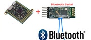
Utiliser un module Bluetooth série avec PyBoard. Dupliquer REPL sur Bluetooth.
Créé par Meurisse D. pour MCHobby.be - Created by Meurisse D. for MCHobby.be
Every reference, text extract of this document should be accompagned with the following credit text : « produced/translated by MCHobby (www.MCHobby.be) - shop for kit and componants » together with a link to the source (so this page). The credit text must be applied on every type of media.
The commercial usage of this text/translation/project's content may be subject to royality fee. In every use case, you must also have the agreement of the initial owner (concerns translation work and content reuse)