Différences entre versions de « ENG-CANSAT-RFM69HCW-TEST »
| Ligne 353 : | Ligne 353 : | ||
The Serial Console also displays the RSSI which indicates the quality of the radio signal (-15 is the best signal we could have, -60 as displayed on the screen is a really bad signal). | The Serial Console also displays the RSSI which indicates the quality of the radio signal (-15 is the best signal we could have, -60 as displayed on the screen is a really bad signal). | ||
| + | == More info == | ||
| + | Reading the sketch would help to understand how the code works. | ||
| + | |||
| + | Those Adafruit examples codes are also documented on the on [https://learn.adafruit.com/adafruit-rfm69hcw-and-rfm96-rfm95-rfm98-lora-packet-padio-breakouts/using-the-rfm69-radio#setup-9-36 this page of the ''Adafruit Learning System'']. | ||
{{ENG-CANSAT-TRAILER}} | {{ENG-CANSAT-TRAILER}} | ||
Version du 12 octobre 2018 à 17:48
Forewords
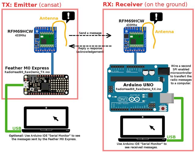
It is now time to establish a communication between:
- a Data Emitter made with a Feather M0 Express + RFM69HCW-433MHz.
- a Data Receiver made with the second RFM69HCW that should be linked to a second micro controller.
As the kit contains only one micro controller (the Feather M0 Express), we will use the very common Arduino UNO (not included) as micro controller for the Data Receiver.
In this simple exemple:
- The Data Emitter will send a message and wait 500ms for a response.
- The Data Receiver will receive the message.
- The Data Receiver will send a reply.
As we will see, there are 2 key items will be highlighted:
- The frequency must be identical in the emitter and receiver (eg: 433.0 MHz in this example).
- The encryption key must be identical on the both side.
Installing the RadioHead library
If not done yet, we will have to install the RadioHead library in Arduino IDE.
That library support lot of RFM modules including our RFM69HCW.
Adafruit did fork the RadioHead library and add some useful sample, so we will install the small|Adafruit's RadioHead forked library.
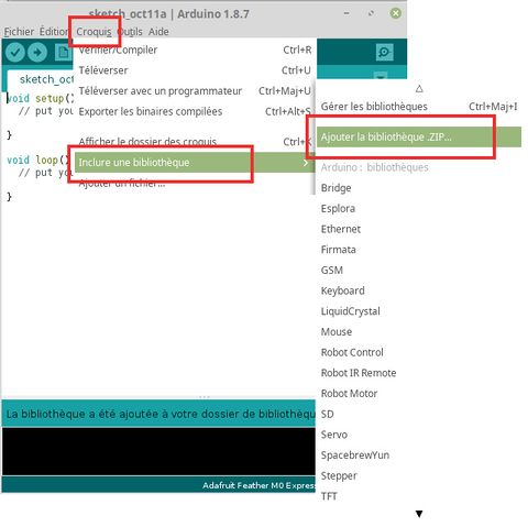
For easy install, you can run Arduino IDE and open the menu "Sketch -> Add a .ZIP library..."
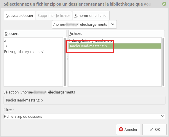
Then pick-up the downloaded RadioHead ZIP file.
| A good idea would be to rename the RadioHead-master.zip to RadioHead.zip before adding it to Arduino IDE. |
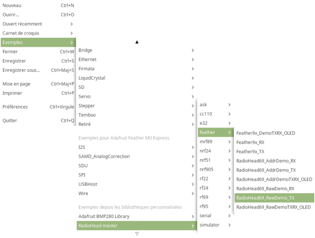
Once installed the RFM69 examples are available from the menu "File -> Examples".
We will focus our interest in the following examples:
- File -> Examples -> RadioHead -> Feather -> RadioHead69_RawDemo_RX
- File -> Examples -> RadioHead -> Feather -> RadioHead69_RawDemo_TX
About Antennas
| The RFM69HCW will not work without antenna, even at 1m distance of each other. |
For this example, a simple wire twisted in the antenna hole will do a great job for testing.
Please wait before soldering the wire inside the antenna hole!. The antenna hole can be populated with:
- a simple wire
- a µFl SMT antenna connector where you could plug various kind of antenna.
- a PCB SMA Connector where you could plus various kind of antenna.
A µFl connector (also named uFl) is locking to this:
A PCB SMA Connector is locking to this:
Frequency, Encryption & Power
To make the module communicating together:
- The module must be identical. You cannot mix them.
- The tuned frequency must be identical.
- The encryption key must be identical.
Tuned frequency
The tuned frequency is declared with a line like this:
#define RF69_FREQ 433.0

...

if (!rf69.setFrequency(RF69_FREQ)) {
    Serial.println("setFrequency failed");
}
where the tuned frequency is declared with the constant RF69_FREQ.
Encyption Key
The module encrypts the data with AES-128.
The encryption key is defined into the following lines.
// The encryption key has to be the same as the one in the server
uint8_t key[] = { 0x01, 0x02, 0x03, 0x04, 0x05, 0x06, 0x07, 0x08,
                  0x01, 0x02, 0x03, 0x04, 0x05, 0x06, 0x07, 0x08};
rf69.setEncryptionKey(key);
Transmission Power
The transmission power is set with the function call.
The range of power is 14 to 20 (in dBi). Lowest values requires less power. Means higher battery life but also smaller transmission distance.
rf69.setTxPower(20, true);
Notice: the second parameter concerns the HCW radio modules and indicates that extra amplifier is present.
The Emitter
We will prepare our message emitter, typically stored inside the CanSat can.
This will involve:
- The Feather M0 Express plateform
- One of the RFM69HCW 433 Mhz module
- An wire antenna
To ease the learning, we will also connect the Feather to the computer to spy the emitted messages (which implies additional code to activate the serial port.
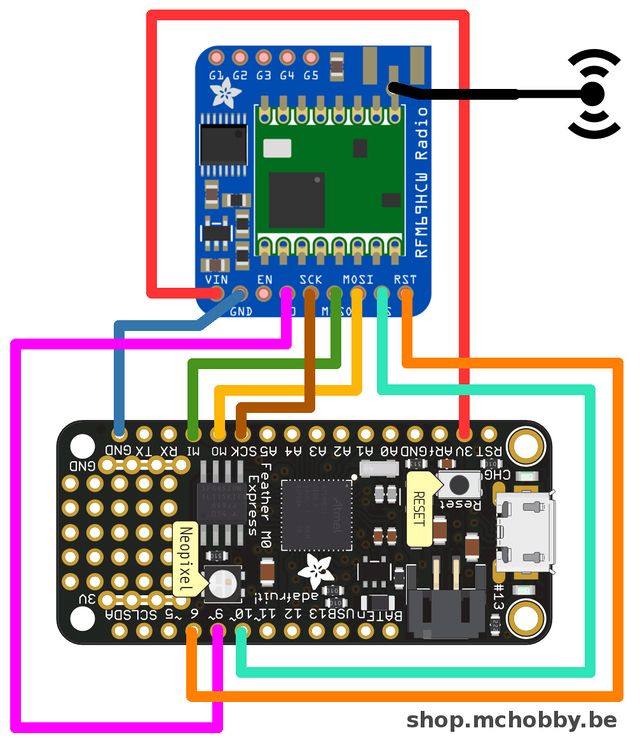
Wiring
| Feather M0 Express | RFM69 |
| 3V | VIN |
| GND | GND |
| MO | MOSI |
| MI | MISO |
| SCK | SCK |
| 6 | CS |
| 9 | G0 |
| 10 | RST |
The code
Now we will load the emitter example code from the RadioHead Library.
Load the sketch file -> Examples -> RadioHead (or RadioHead-master) -> feather -> RadioHead69_RawDemo_TX
| We will have to modify the code before uploading it to the Feather M0 Express! |
Indeed, the example code is provided for the Feather M0 and not the Feather M0 Express so we will have to adapt the used pinout because pins 3,4 and 8 are not available on the Feather M0 Express.
Update for Interface:
Locate the following lines in the code:
#if defined(ARDUINO_SAMD_FEATHER_M0) // Feather M0 w/Radio
  #define RFM69_CS      8
  #define RFM69_INT     3
  #define RFM69_RST     4
  #define LED           13
#endif
and change it as follow ("Feather M0 Express" it is still the a "Feather M0" plateform):
#if defined(ARDUINO_SAMD_FEATHER_M0)
  // UPDATE for Feather M0 EXPRESS with RFM69HCW radio module
  // G0 is the Radio Module interrupt pin
  #define RFM69_CS      6
  #define RFM69_INT     9
  #define RFM69_RST     10
  #define LED           13
#endif
Update for frequency plan:
The RFM69HCW exists in 2 flavor:
- 900 MHz for United State usage (with a green dot)
- 433 Mhz for "Europe" license-free ISM usage (with a red dot ).
The code is the same for the both flavor, you must indicates the right frequency according to the module you have. Trying to generate 900Mhz signal on a 433Mhz would result in "nothing generated"!
The RFM69HCW 433Mhz can generate signal from 424 Mhz to 510 Mhz (see datasheet). You have to select the Frequency accordingly to the authorised Frequency Plan and Radio License. The 433 Mhz is free for use, please select your own frequency in that range.
Locate the following lignes:
// Change to 434.0 or other frequency, must match RX's freq!
#define RF69_FREQ 915.0
And update it to:
// Change to 434.0 or other frequency, must match RX's freq!
#define RF69_FREQ 433.0
Activate the Serial Line:
The begin of the setup() function does contains the following lines.
void setup()
{
  Serial.begin(115200);
  //while (!Serial) { delay(1); } // wait until serial console is open, remove if not tethered to computer
Update it and remove the comment mark in the front of the while loop like showed here under.
void setup()
{
  Serial.begin(115200);
  while (!Serial) { delay(1); } // wait until serial console is open, remove if not tethered to computer
This way, the Feather will wait for the "serial monitor" to be open before starting the sketch.
This while loop is important otherwise, none of the serial.print() would be visible in the serial monitor.
Voilà, We are ready to compile and upload.
Compile and upload
Select the proper board in the menu Tools -> Type of board : Adafruit Feather M0 Express
Select the proper port in the menu Tools -> Port
Then press the "compile" button.
| If you add trouble to flash the Feather, you can still activate manually the boot mode by double pressing the reset button before compiling the sketch. |
Running the sketch
Now open the Serial Monitor and set the baud rate to 115200 baud.
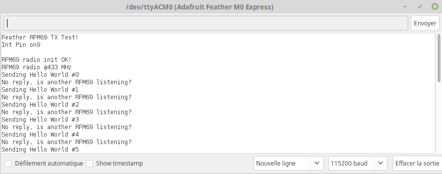
As there is no board listening and answering, you should see the following results on the screen.
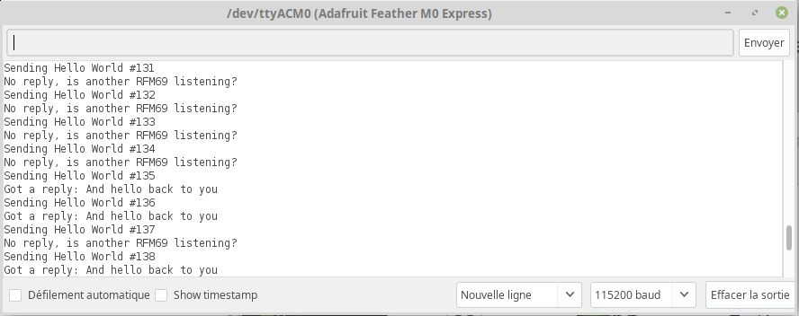
Later, when the the receiver would be ready, the message will turn from "Is another RFM69 Listening?" to "Got reply:"
The Receiver
Now we will prepare our receiver station.
The receiver stays on the ground and receive the messages sent by the Emitter and forward them to a computer.
This will involve:
- The second RFM69HCW 433 Mhz module
- An arduino compatible microcontroler (we selected an Arduino Uno)
- A computer to read the messages
- An wire antenna
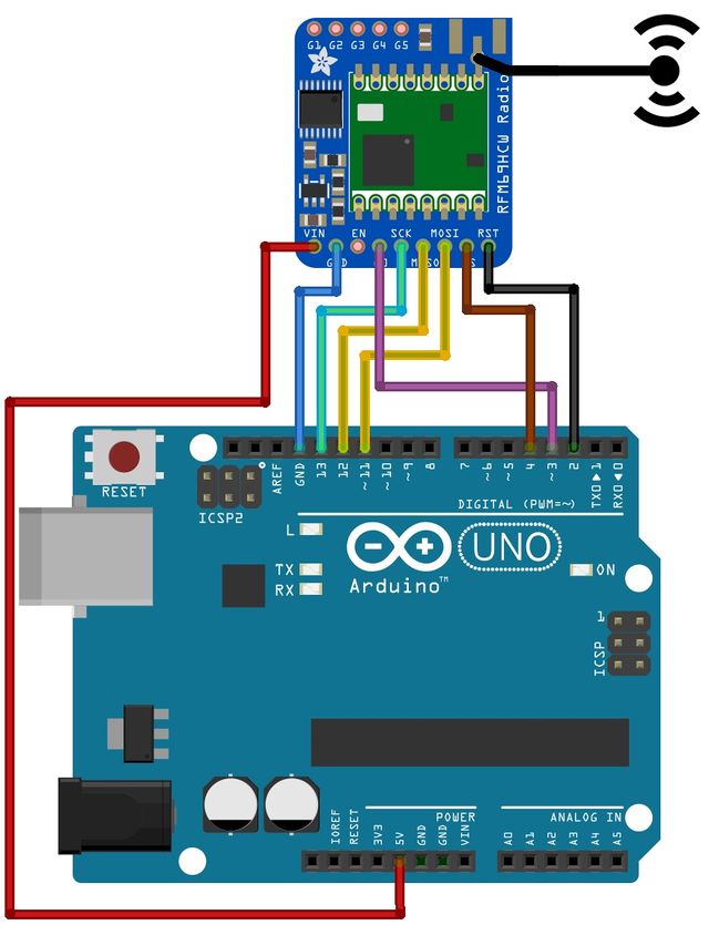
Wiring
| Feather M0 Express | RFM69 |
| 5V | VIN |
| GND | GND |
| 11 | MOSI |
| 12 | MISO |
| 13 | SCK |
| 4 | CS |
| 3 | G0 |
| 2 | RST |
The code
Now we will load the receiver example code from the RadioHead Library.
Load the sketch file -> Examples -> RadioHead (or RadioHead-master) -> feather -> RadioHead69_RawDemo_RX
| We will have to modify the code before uploading it to the Arduino Uno! |
Update for Interface:
No update are required for the interface as we the following the wiring for ATmega328P:
#if defined (__AVR_ATmega328P__)  // Feather 328P w/wing
  #define RFM69_INT     3  //
  #define RFM69_CS      4  //
  #define RFM69_RST     2  // "A"
  #define LED           13
#endif
Update for frequency plan:
The frequency used by the receiver RFM69HCW must be exactly the same as th emitter! z is free for use, please select your own frequency in that range.
Locate the following lignes:
// Change to 434.0 or other frequency, must match RX's freq!
#define RF69_FREQ 915.0
And update it to:
// Change to 434.0 or other frequency, must match RX's freq!
#define RF69_FREQ 433.0
Activate the Serial Line:
No need to change here as we are using an Arduino UNO.
Voilà, We are ready to compile and upload.
Compile and upload
Select the proper board in the menu Tools -> Type of board : Arduino/Genuino UNO
Select the proper port in the menu Tools -> Port
Then press the "compile" button.
Running the sketch
Now open the Serial Monitor and set the baud rate to 115200 baud.
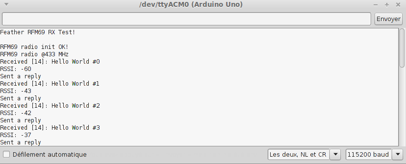
As we did already started the "emitter" board, the receiver board will immediately display the received message and sends replies.
The Serial Console also displays the RSSI which indicates the quality of the radio signal (-15 is the best signal we could have, -60 as displayed on the screen is a really bad signal).
More info
Reading the sketch would help to understand how the code works.
Those Adafruit examples codes are also documented on the on this page of the Adafruit Learning System.
Written by Meurisse D. from MC Hobby - License: CC-SA-BY.
